Ford Ranger EV (2001 year). Manual - part 40
 

  Index      Ford     Ford Ranger EV - service repair manual 2001 year


Search            


Content   ..  38  39  40  41   ..


Ford Ranger EV (2001 year). Manual - part 40


206-07-10

206-07-10

Power Brake Actuation

REMOVAL AND INSTALLATION (Continued)

Vacuum Pump

Removal

1.

Disconnect the auxiliary battery ground cable.

2.

Raise and support the vehicle. For additional
informstion, refer to 

 Section 100-02

.

3.

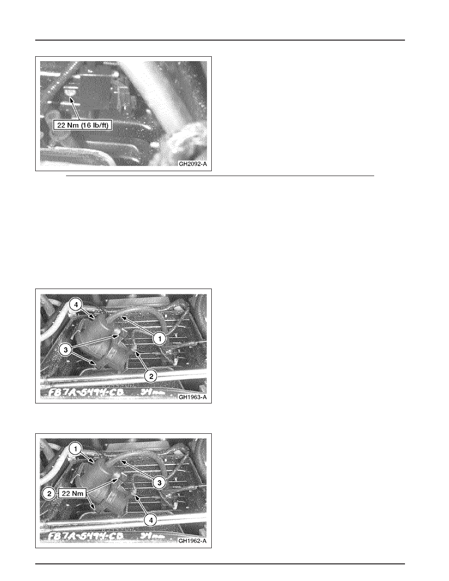
Remove the vacuum pump.

1

Disconnect the vacuum line.

2

Disconnect the electrical connector.

3

Remove the pump bracket bolts.

4

Remove the pump.

Installation

1.

Install the vacuum pump.

1

Position the vacuum pump.

2

Install the pump bracket bolts.

3

Connect the vacuum line.

4

Connect the electrical connector.

206-07-11

206-07-11

Power Brake Actuation

REMOVAL AND INSTALLATION (Continued)

2.

Connect the traction battery. For additional
information, refer to 

 Section 414-03A 

 or 

Section 414-03B

.

206-09-1

206-09-1

Anti-Lock Control

Manual Table of Contents

SECTION 206-09 Anti-Lock Control

VEHICLE APPLICATION:

Ranger EV

CONTENTS

PAGE

SPECIFICATIONS ....................................................................................... 

206-09-2

DESCRIPTION AND OPERATION

Anti-Lock Brake and Regenerative Braking System ............................................. 

206-09-2

Hydraulic Control Unit ................................................................................ 

206-09-2

DIAGNOSIS AND TESTING

Anti-Lock Control ...................................................................................... 

206-09-3

Active Command Index ............................................................................ 

206-09-5

Diagnostic Trouble Code (DTC) Definition ..................................................... 

206-09-3

Electrical Schematic ............................................................................... 

206-09-4

Inspection and Verification ........................................................................ 

206-09-4

Parameter Identification (PID) Index ............................................................ 

206-09-4

Pinpoint Tests ....................................................................................... 

206-09-6

Symptom Chart ..................................................................................... 

206-09-5

REMOVAL AND INSTALLATION

Anti-Lock Brake Control Module .................................................................. 

206-09-13

Anti-Lock Brake Sensor —Front .................................................................. 

206-09-15

Anti-Lock Brake Sensor —Rear .................................................................. 

206-09-15

Hydraulic Control Unit .............................................................................. 

206-09-16

206-09-2

206-09-2

Anti-Lock Control

SPECIFICATIONS

Torque Specifications

Torque Specifications

Description

Nm

Lb-Ft

Lb-In

Description

Nm

Lb-Ft

Lb-In

Battery Ground Cable

6.2

53.5

Anti-Lock Brake

2

16 

Control Module Screws

Brake Line Fittings

18

13

Anti-Lock Brake Sensor

6

54

Hydraulic Control Unit

9

80

Bolt

(HCU) Anti-Lock Brake

Control Module

Anti-Lock Brake Sensor

12

107

Assembly Bracket Bolts

Harness Bracket Bolt

(Continued)

DESCRIPTION AND OPERATION

Hydraulic Control Unit

Anti-Lock Brake and Regenerative

The hydraulic control unit (HCU) uses six electric

Braking System

solenoids to control brake fluid flow to the front
and rear wheels. The front wheels are on two

The anti-lock brake system (ABS) on the Electric

separate circuits and the rear wheels are on a single

Ranger is a Teves Mark 20i-based system that uses

circuit. The anti-lock brake control module  bolts to

four anti-lock brake sensors. A sensor mounted at

the HCU and provides the electronic signals to the

each of the four wheels provides wheel speed

HCU to control solenoid operation. Wheel speed

information to the anti-lock brake control module,

information is fed to the ABS module by anti-lock

which operates the ABS to efficiently stop the

brake sensors. If the module senses that a wheel is

vehicle.

about to lock up, the solenoid for that  wheel will

The regenerative braking system recovers vehicle

be activated to control braking.

kinetic energy during deceleration to replace traction
battery energy. A certain level of regenerative
braking is commanded by releasing the accelerator
pedal. Further regenerative braking is commanded
by pressing the brake pedal. During deceleration,
the motor/transaxle is turned by the vehicle’s
wheels. When the vehicle is operated in the
economy (E) mode, the effects of regenerative
braking are increased. Whenever the ABS is
activated,  regenerative braking is disabled until the
ABS event is over and the accelerator pedal is
pressed.


Content   ..  38  39  40  41   ..