Ford Falcon. Manual - part 479
 

  Index      Ford     Ford Falcon - service repair manual 2002-2005 year


Search            


Content   ..  477  478  479  480   ..


Ford Falcon. Manual - part 479


501-20b-131 

Occupant Restraints — Passive 

501-20b-131

GENERAL PROCEDURES (Continued)

replacing any front or side airbag supplemental

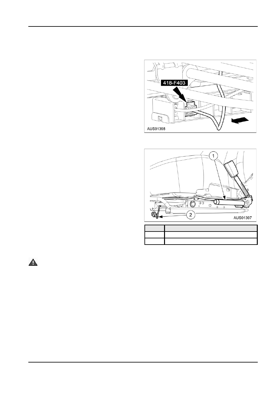
1.  From under the front LH seat, remove the

restraint system (SRS) components and before

restraint system diagnostic tool from the safety

servicing, replacing, adjusting or striking

belt buckle pretensioner electrical connector.

components near the front or side airbag sensors,

such as doors, instrument panel, console, door

latches, strikers, seats and hood latches.

The side impact sensors (if equipped) are located

at or near the base of the B-pillars.

To deplete the backup power supply energy,

disconnect the battery ground cable and wait at

least one minute. Be sure to disconnect auxiliary

batteries and power supplies (if equipped).
NOTE: 
If a seat equipped with a seat mounted side

airbag and/or a safety belt pretensioner (if equipped)

system is being serviced, the airbag system must

be deactivated.

NOTE: Restraint system diagnostic tools MUST be

installed under the seats in the seat side airbag (if

2.  From under the front LH seat, connect the safety

equipped) and safety belt pretensioner.

belt buckle pretensioner electrical connector.

NOTE: Diagnostics or repairs are not to be performed

on a seat equipped with a seat side airbag with the

seat in the vehicle. Prior to attempting to diagnose or

repair a seat concern when equipped with a seat side

airbag, the seat must be removed from the vehicle

and the restraint system diagnostic tools must be

installed in the seat side airbag electrical connectors.

The restraint system diagnostic tools must be

removed prior to operating the vehicle over the

road.

NOTE: After diagnosing or repairing an SRS, the

restraint system diagnostic tools must be

removed before operating the vehicle over the

road.

NOTE: The SRS must be fully operational and free of

Item

Description

faults before releasing the vehicle to the customer.

1

Seat belt pretensioners

1.  Remove drivers airbag module as described later

2

Pretensioner electrical connector

in this section.

Reactivation

 WARNING: To reduce the risk of serious

personal injury, read and follow all warnings,

cautions, and notes at the beginning of the

deactivation procedure.
NOTE: 
Make sure the negative battery cable is still

disconnected before continuing with the reactivation

portion of this procedure.

G12355 en

501-20b-132 

Occupant Restraints — Passive 

501-20b-132

GENERAL PROCEDURES (Continued)

3.  From under the front RH seat, remove the

servicing, replacing, adjusting or striking

restraint system diagnostic tool from the safety

components near the front or side airbag sensors,

belt buckle pretensioner electrical connector.

such as doors, instrument panel, console, door

latches, strikers, seats and hood latches.

The side impact sensors (if equipped) are located

at or near the base of the B-pillars.

To deplete the backup power supply energy,

disconnect the battery ground cable and wait at

least one minute. Be sure to disconnect auxiliary

batteries and power supplies (if equipped).
1.  Disconnect the battery ground cable and wait at

least one minute. For additional information, refer

to Section 414-01.

All vehicles

NOTE: Make sure the negative battery cable is still

disconnected before continuing with the reactivation

portion of this procedure.

4.  From under the front RH seat, connect the safety

1.  Remove the restraint system diagnostic tool from

belt buckle pretensioner electrical connector.

the vehicle harness side of the passenger airbag

module electrical connector.

Item

Description

2.  Connect the passenger airbag module electrical

1

Seat belt pretensioners

connector.

2

Pretensioner electrical connector

Vehicles with power seats

1.  Connect the battery ground cable. For additional

information, refer to Section 414-01.

All vehicles

1.  Position the front seats rearward.
Vehicles with power seats

 WARNING: To avoid accidental deployment

and possible personal injury, the backup power

supply must be depleted before repairing or

replacing any front or side airbag supplemental

restraint system (SRS) components and before

G12355 en

501-20b-133 

Occupant Restraints — Passive 

501-20b-133

GENERAL PROCEDURES (Continued)

3.  Remove the restraint system diagnostic tool from

7.  Position the driver airbag module to the steering

the vehicle harness side of the passenger airbag

wheel.

electrical connector.


1.  Connect the horn switch electrical connector.

 CAUTION: The clockspring electrical

connectors are unique and cannot be

reversed when connected to the driver

airbag module. Match the electrical

connector key to the keyway in the driver

airbag module. Do not force the electrical

connectors into the driver airbag module.


2.  Connect the driver airbag module electrical

connectors as noted during removal.


3.  Position the driver airbag module to the

steering wheel.

4.  Connect the passenger airbag module electrical

connector.

Item

Description

1

Clokspring LH connector

2

Clokspring RH connector

5.  Close the glove compartment.

3

Steering wheel audio controls connector

6.  Remove the restraint system diagnostic tools from

NOTE: Make sure the negative battery cable is still

the clockspring electrical connector at the top of

disconnected before continuing with the installation

the steering column.

portion of this procedure.

8.  Remove the restraint system diagnostic tool from

the clockspring electrical connector at the top of

the steering column.

G12355 en

501-20b-134 

Occupant Restraints — Passive 

501-20b-134

GENERAL PROCEDURES (Continued)

9.  Position the driver airbag module to the steering

12. With all the restraint system diagnostic tools

wheel.

removed, prove out the supplemental restraint

system (SRS). For additional information, refer to


1.  Connect the driver airbag module electrical

the Airbag and Safety Belt Pretensioner

connector.

Supplemental Restraint System (SRS) in the


2.  Slide and engage the driver airbag module

Diagnosis and Testing portion of Section 501-20b.

electrical connector locking clip.


3.  Connect the horn switch electrical connector.

Weld Nut Repair — Missing Weld Nut


4.  Position the driver airbag module to the

steering wheel.

 WARNING: To avoid accidental deployment

and possible personal injury, the backup power


5.  Push driver airbag module assembly until

supply must be depleted before repairing or

seats into the steering wheel.

replacing any front or side airbag supplemental

restraint system (SRS) components and before

servicing, replacing, adjusting or striking

components near the front or side airbag sensors,

such as doors, instrument panel, console, door

latches, strikers, seats and hood latches.

The side impact sensors (if equipped) are located

at or near the base of the B-pillars.

To deplete the backup power supply energy,

disconnect the battery ground cable and wait at

least one minute. Be sure to disconnect auxiliary

batteries and power supplies (if equipped).

 CAUTION: Installing a J-nut in place of a weld

nut is not a recommended repair.
NOTE: 
C-pillar repair shown, others similar.

Item

Description

1.  Remove the component from where the weld nut

1

Clokspring LH connector

is to be repaired.

2

Clokspring RH connector

2.  Drill three equally spaced in 1.75mm (5/64) holes

3

Steering wheel audio controls connector

in close proximity to where the weld nut face will

be plug welded back to the sheet metal.

10. Install the two driver airbag module bolts (one

shown). Rotate wheel 90

° to access airbag

attachment rotate again in oppsite direction to

make second attachment.

3.  Obtain the appropriate 6 mm (0.24in) or 8mm

(0.32in) weld nut.

4.  Obtain the appropriate 6 mm (0.24in) by 1.0 or

8mm (0.32in) by 1.25 grounding screw

11. Connect the battery ground cable. For additional

(self-tapping).

information, refer to Section 414-01.

 WARNING: The restraint system

diagnostic tool is for restraint system service

only. Remove from the vehicle prior to road

use. Failure to remove could result in injury

and possible violation of vehicle safety

standards.

G12355 en


Content   ..  477  478  479  480   ..