Ford Falcon. Manual - part 434
501-14-15
Handles, Locks, Latches and Entry Systems
501-14-15
DISASSEMBLY AND ASSEMBLY (Continued)
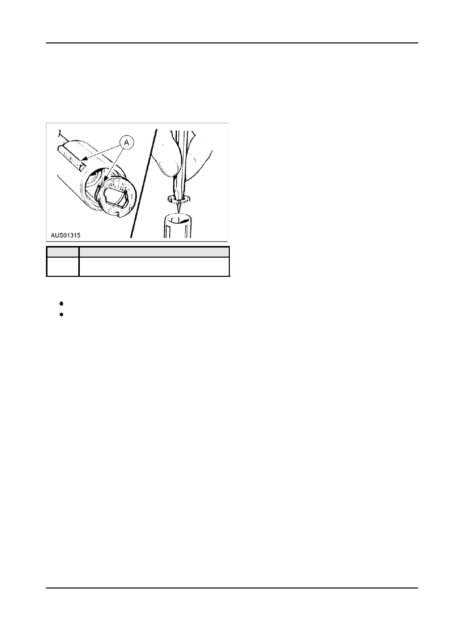
2. Insert the first tumbler into the magazine ensuring
that the roller cutout is on the same side as the
roller slot in the magazine. Follow this with a
spacer, ensuring that the roller cutout aligns with
the roller slot. The first tumbler inserted (using our
example) should be a ‘3’.
Item
Description
A
Make sure roller slot and tumbler cut out
are on the same side.
3. Again, following our example, the remaining
tumblers are inserted in the following order:
2 + spacer, 4 + spacer, 3 + spacer,
4 + pack spring (wave washer) and finally the
last tumbler ‘1’.
This completes our key code example
143423.
4. Apply powdered graphite to the centre of the
magazine and to the magazine casing. At this
stage check that the roller descends/rises when
the key is inserted and turned, and that there is 0
°
free play to lock and 45
° free play before
unlocking.
5. Fit the end cap to the magazine, clamp it in a soft
jawed vice and using an automatic centre punch,
deform the castellations to secure the assembly.
6. Lubricate and insert the semi-circular shutter into
the magazine by holding the thin tapered end of
the shutter between the finger and thumb and
passing the thicker end under the two side tabs,
so that the thicker end of the shutter sits over the
centre of the lock.
7. Lubricate the roller and insert it into the roller slot.
8. Assemble the magazine into the housing by
aligning the roller to the roller recess in the
housing and sliding it in. Secure the magazine in
the housing by fitting the smaller circlip.
9. Refit the large circlip to the magazine so that its
open end is opposite the small raised tang on the
magazine.
G31892 en