Ford Falcon. Manual - part 382
 

  Index      Ford     Ford Falcon - service repair manual 2002-2005 year


Search            


Content   ..  380  381  382  383   ..


Ford Falcon. Manual - part 382


417-02-7 Interior 

Lighting 417-02-7

REMOVAL AND INSTALLATION

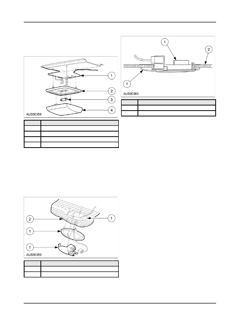
Interior Lamp

Removal
1.  Unclip the interior lamp lens.

Item

Description

1

Bezel

2

Roof Trim Panel

2.  Remove the bulb from the lamp.

Item

Description

Installation

1

Roof Trim Panel

1.  Install the bulb into the lens.

2

Bezel

2.  Refit the lens into the bezel, inserting the knob

3

Bulb

end first.

4

Lens

Front Vanity Lamp

2.  Remove the bulb.

Removal

Installation

Refer to Map Reading Lamp removal.

1.  Install lamp bulb.

Installation

2.  Refit the interior lamp lens.

Refer to Map Reading Lamp installation.

Map Reading Lamp

Luggage Compartment Lamp —

Removal

Wagon

1.  Unclip the lens from the bezel using a screwdriver

Removal

on the end of the lens opposite the knob.

1.  Refer to Map Reading Lamp removal.
Installation
1.  Refer to Map Reading Lamp installation.

Item

Description

1

Bezel

2

Roof Trim Panel

G46754 en

417-02-8 Interior 

Lighting 417-02-8

REMOVAL AND INSTALLATION (Continued)

Luggage Compartment Lamp — Sedan

Removal
1.  Remove lamp as shown.

Item

Description

1

Black Insulator (earth)

2

Negative earth

3

Negative

4

Positive

5

Positive Insulator

6

Red Insulator (feed)

Installation
1.  Reverse removal procedure.

Console Lamp (Lo Series)

Removal
1.  Remove console lamp as shown in figure.

Installation
1.  Reverse removal procedure.

Console Lamp (High Series)

Refer to Section 501-05.

G46754 en

418-00-1 

Module Communications Network 

418-00-1

SECTION : 418-00 Module Communications

Network

VEHICLE APPLICATION : 2003.0 BA Falcon
CONTENTS  

PAGE

SPECIFICATIONS

 Specifications   ........................................................................................................................418-00-2

DESCRIPTION AND OPERATION

  Communications Network   .....................................................................................................418-00-3

DIAGNOSIS AND TESTING

  Communications Network   .....................................................................................................418-00-4

  Principles of Operation  .........................................................................................................418-00-4

  Inspection and Verification  ...................................................................................................418-00-4

 Symptom 

Chart 


....................................................................................................................418-00-4

  Connector Circuit Reference  ................................................................................................418-00-5

 Pinpoint 

Tests 


......................................................................................................................418-00-9

GENERAL PROCEDURES

  Communication Circuit Wiring Repair   .................................................................................418-00-22

418-00-2 

Module Communications Network 

418-00-2

SPECIFICATIONS

General Specifications

Description

Specification

Heat shrink tube overlap

12.7 (0.5)

mm (inch)
Wire insulation removal

37.2 (1.5)

length (twist side) mm

(inch)
Wire insulation removal

19.5 (0.75)

length (receiving side)

mm (inch)
Raychem SCT® Heat

ESB-M99D56-A2

Shrink Tubing, Motorcraft

part number WT-5627

G86726 en


Content   ..  380  381  382  383   ..