Ford Falcon. Manual - part 371
 

  Index      Ford     Ford Falcon - service repair manual 2002-2005 year


Search            


Content   ..  369  370  371  372   ..


Ford Falcon. Manual - part 371


417-01-23 Exterior 

Lighting 417-01-23

DIAGNOSIS AND TESTING (Continued)

The hazard lamps are inoperative

Possible causes:

Circuit 383C (Y) open or short to ground
Cluster C-171

PINPOINT TEST K : THE HAZARD LAMPS ARE INOPERATIVE

Test Step

Result / Action to Take

K1

CHECK CIRCUIT 383C (Y) VOLTAGE

Disconnect: cluster.

Yes

Perform the cluster testing in Section 413-01.

Measure the voltage between cluster C-171, circuit 383C (Y), harness Test the system for normal operation.

side and ground.

No

Is the voltage greater than 10 volts?

Repair circuit 383C (Y).
Test the system for normal operation.

Stop Lamps
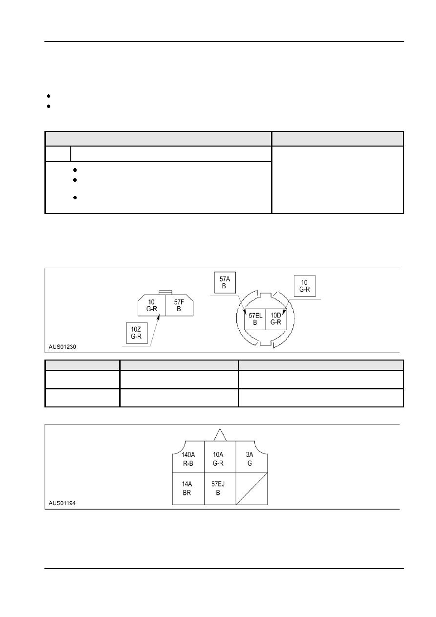
Connector Circuit Reference

C-39 High Mount Stop Lamp

Pin Number(s)

Circuit Designation/Description

Normal Condition/Measurement

1

Circuit 10D (G-R)

0 voltage, less than 5 ohms between stop lamp

Stop lamp power input

and brake switch

2

Circuit 57EL (B)

0 voltage, less than 5 ohms between stop lamp

Stop lamp ground

and chassis ground

C-44 Wagon LH Tail Lamp

G86730 en

417-01-24 Exterior 

Lighting 417-01-24

DIAGNOSIS AND TESTING (Continued)

Pin Number(s)

Circuit Designation/Description

Normal Condition/Measurement

1

Circuit 10A (G-R)

0 voltage, less than 5 ohms between stop lamp

Stop lamp power input

and brake switch

2

Circuit 57EJ (B)

0 voltage, less than 5 ohms between LH tail

LH tail lamp ground

lamp and chassis ground

C-45 Wagon RH Tail Lamp

Pin Number(s)

Circuit Designation/Description

Normal Condition/Measurement

1

Circuit 10B (G-R)

0 voltage, less than 5 ohms between stop lamp

Stop lamp power input

and brake switch

2

Circuit 57EK (B)

0 voltage, less than 5 ohms between RH tail

RH tail lamp ground

lamp and chassis ground

C-77 Sedan Right Tail Lamp

Pin Number(s)

Circuit Designation/Description

Normal Condition/Measurement

1

Circuit 10B (G-R)

0 voltage, less than 5 ohms between stop lamp

Stop lamp power input

and brake switch

2

Circuit 57EK (B)

0 voltage, less than 5 ohms between RH tail

RH tail lamp ground

lamp and chassis ground

C-78 Sedan Left Tail Lamp C-78

G86730 en

417-01-25 Exterior 

Lighting 417-01-25

DIAGNOSIS AND TESTING (Continued)

Pin Number(s)

Circuit Designation/Description

Normal Condition/Measurement

1

Circuit 10A (G-R)

0 voltage, less than 5 ohms between stop lamp

Stop lamp power input

and brake switch

2

Circuit 57EJ (B)

0 voltage, less than 5 ohms between LH tail

LH tail lamp ground

lamp and chassis ground

C-191 Brake Switch

Pin Number(s)

Circuit Designation/Description

Normal Condition/Measurement

1

Circuit 10AA (G-R)

0 voltage, less than 5 ohms between the brake

Brake switch power input

switch and ignition relay

2

Circuit 10Y (G-R)

0 voltage, less than 5 ohms between the brake

Brake switch output to stop lamps switch and stop lamps

C-710 Ute After Market High Mount Stop Lamp

Pin Number(s)

Circuit Designation/Description

Normal Condition/Measurement

1

Circuit 10C (G-R)

0 voltage, less than 5 ohms between stop lamp

Stop lamp power input

and brake switch

2

Circuit 140M (R-B)

0 voltage, less than 5 ohms between stop lamp

and reverse lamps

C-705 Ute Cab Chassis RH Tail Lamp

G86730 en

417-01-26 Exterior 

Lighting 417-01-26

DIAGNOSIS AND TESTING (Continued)

Pin Number(s)

Circuit Designation/Description

Normal Condition/Measurement

1

Circuit 10A (G-R)

0 voltage, less than 5 ohms between stop lamp

Stop lamp power input

and brake switch

2

Circuit 57A (B)

0 voltage, less than 5 ohms between stop lamp

Stop lamp ground

and chassis ground

C-707 Ute Cab Chassis LH Tail Lamp

Pin Number(s)

Circuit Designation/Description

Normal Condition/Measurement

1

Circuit 10C (G-R)

0 voltage, less than 5 ohms between stop lamp

Stop lamp power input

and brake switch

2

Circuit 57B (B)

0 voltage, less than 5 ohms between stop lamp

Stop lamp ground

and chassis ground

C-706 Ute Style Side Box RH Tail Lamp

Pin Number(s)

Circuit Designation/Description

Normal Condition/Measurement

1

Circuit 10A (G-R)

0 voltage, less than 5 ohms between stop lamp

Stop lamp power input

and brake switch

2

Circuit 57B (B)

0 voltage, less than 5 ohms between stop lamp

Stop lamp ground

and chassis ground

C-708 Ute Style Side Box LH Tail Lamp

G86730 en


Content   ..  369  370  371  372   ..