Ford Falcon. Manual - part 326
412-04-17 Control
Components 412-04-17
DIAGNOSIS AND TESTING (Continued)
Test Step
Result / Action to Take
B4
MODULE FUNCTION CHECK - EVAPORATOR SENSOR
TEMPERATURE
Reconnect the sensor 2 way connector D to the HIM.
Yes
System OK.
Connect WDS Scan Tool.
No
Read the A_CT value (Evaporator sensor temperature) from the HIM.
Go to B5
Does the value closely match the temperature thermometer
located in the face outlet (+/- 5 degC) as per table B?
B5
MODULE FUNCTION CHECK - EVAPORATOR SENSOR
SUPPLY VOLTAGE
Check the Evaporator sensor supply voltage with a voltmeter.
Yes
Go to B6
With the Evaporator sensor 2 way connector D inserted in to the HIM,
attach the positive probe to pin 2 (LHS) and the negative probe to pin
No
1 (RHS) of the rear of the Evaporator sensor connector. Refer to
Replace HIM.
Evaporative sensor connector diagram for correct pin designations.
Using table B, compare the voltage reading against a temperature
probe located in the face outlet with the HVAC Blower fan operating at
high speed.
Does the voltage value closely match the temperature
thermometer located in the face outlet (+/- 5 degC)?
B6
MODULE OUTPUT CHECK - EVAPORATOR SENSOR
SUPPLY VOLTAGE
Remove evaporator sensor plug from HIM.
Yes
System OK.
Using a voltmeter, attach the probes to the HIM output terminals for
Clear DTC.
the evaporator sensor.
No
Ensure ignition key is ON.
Replace HIM.
Is the voltage reading within 4.5-5.5 Volts?
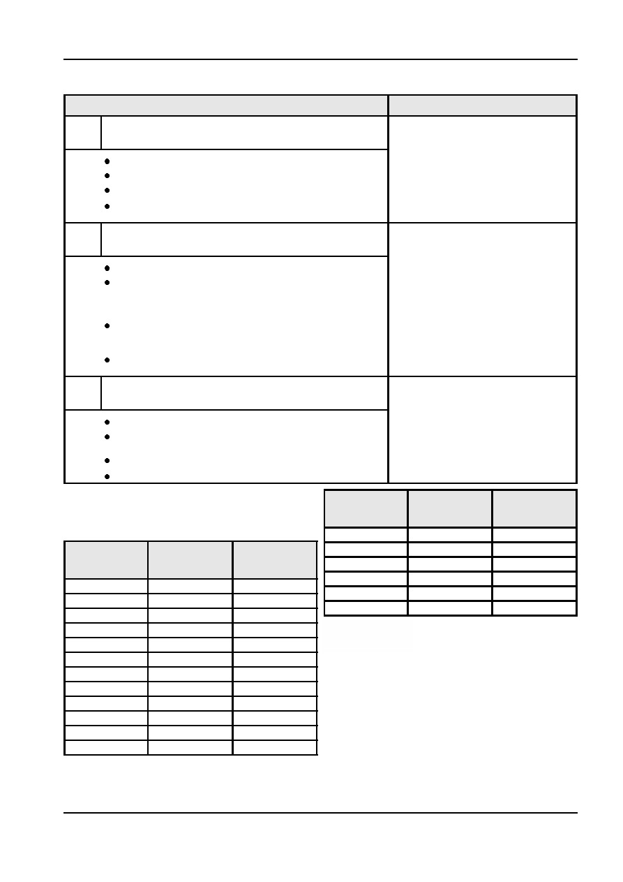
Temperature
Sensor
Sensor Voltage
Table B
Degrees
Resistance
(Volts)
NOTE: Use this table as a guide only. Minor
(Celsius)
(Ohms)
variations between actual readings are acceptable.
30
1.21k
0.96
Temperature
Sensor
Sensor Voltage
35
0.98k
0.81
Degrees
Resistance
(Volts)
40
0.75k
0.68
(Celsius)
(Ohms)
45
0.66k
0.57
-30
25.37k
4.16
50
0.55k
0.48
-25
18.90k
3.94
55
0.45k
0.41
-20
14.19k
3.68
-15
10.73k
3.39
-10
8.17k
3.08
-5
6.27k
2.76
0
4.85k
2.44
5
3.78k
2.13
10
2.97k
1.84
15
2.35k
1.56
20
1.87k
1.34
25
1.50k
1.14
A12342 en