Ford Falcon. Manual - part 325
412-04-13 Control
Components 412-04-13
DIAGNOSIS AND TESTING (Continued)
Pin Number(s)
Circuit Designation/Description
Normal Condition/Measurement
8
Circuit 682 (R)
Resistance (Ohm) between pins 1 and 3
Sensor GND
2.7K ~ 3.3K ohms
11
Circuit 915P (P-L)
Note 1
CAN bus to ICC
12
Circuit 915J (P-L)
Note 1
CAN bus to PCM
13
Circuit 1133 (BR)
Voltage ( V ) to vehicle body electrical ground
Blower Motor
Approximately + Battery ( 12 ~ 14v) while engine
running, blower connected and HIM
disconnected.
14
Circuit 57CB (B)
Resistance (Ohm) to vehicle body electrical
Power GND
ground
0 ohms approx.
CAUTION: Do not probe terminals with any
type of meter as damage to vehicle systems may
result.
CAUTION: Do not insert probes in to front of
terminal, damage may result. Probe only rear (wire
entry) of connectors.
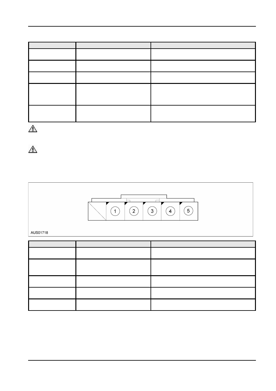
Dual Zone Actuator Terminal Connections 5 way
NOTE: View from wire entry side (rear).
Pin Number(s)
Circuit Designation/Description
Normal Condition/Measurement
1
Potentiometer +
Resistance (Ohm) between pins 1 and 3
2.7K ~ 3.3K ohms
2
Potentiometer
Resistance (Ohm) between pins 2 and 3
Wiper
0 ~ 3.3K ohms (value dependant on motor output
coupling angle)
3
Potentiometer -
Resistance (Ohm) between pins 1 and 3
2.7K ~ 3.3K ohms
4
Motor Connection
Diode (D) Continuity between pins 4 and 5
0.5 ~ 0.7V
5
Motor Connection
Diode (D) Continuity between pins 4 and 5
0.5 ~ 0.7V
HIM Input Connection D (Evaporator Temperature Sensor 2 Way)
NOTE: View from wire entry side (rear).
A12342 en