Ford Falcon. Manual - part 262
308-03a-10
Manual Transmission/Transaxle — I6
308-03a-10
GENERAL PROCEDURES
12. Inspect the synchronizer blocking rings for
Transmission Cleaning
widened index slots, rounded clutch teeth, and
1. Wash all parts except ball bearings, O-rings and
smooth internal surfaces (must have machined
seals in a suitable cleaning solvent. Brush or
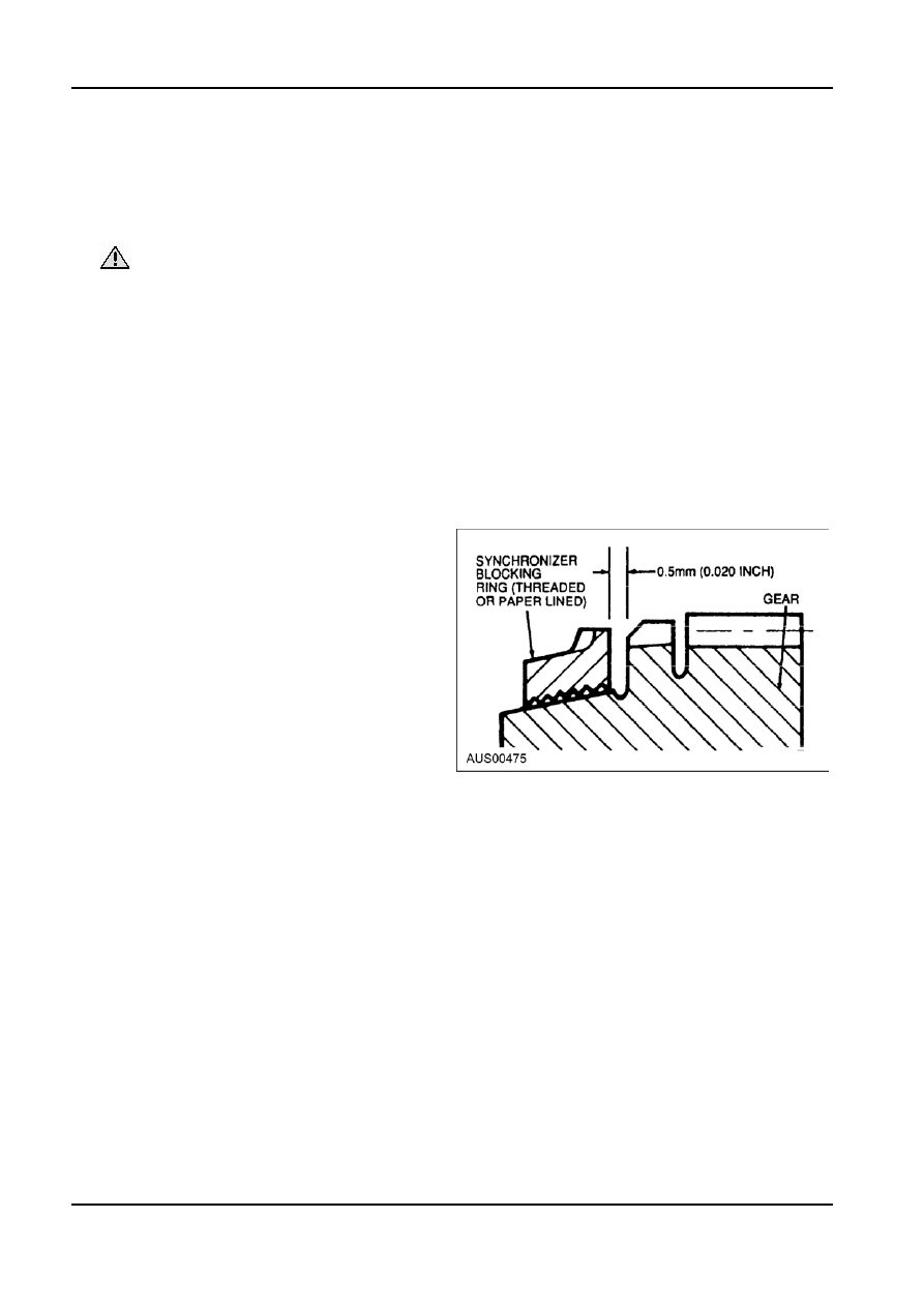
grooves). With the synchronizer blocking ring on
scrape all foreign matter from the parts. Be careful
the cone, the distance between the face of the
not to damage any parts with the scraper.
synchronizer blocking ring and the clutch teeth on
the gear must not be less than 0.5mm (0.020
CAUTION: Do not clean, wash or soak
inch).
transmission seals in cleaning solvents. Dry
13. Replace speedometer drive gear (where fitted) if
all parts with compressed air.
teeth are stripped or damaged. Make certain to
2. Rotate ball bearings in a cleaning solvent until all
install correct size replacement gear.
lubricant is removed. Hold bearing assembly to
14. Replace the output shaft if there is any evidence
prevent it from rotating and dry it with compressed
of wear or if any of the splines are damaged.
air.
15. Inspect bushing and seal in the extension
3. Lubricate bearings with Multi-Purpose Grease and
housing, and replace if worn or damaged. The
wrap them in a clean, lint-free cloth or paper until
bushing and/or seal should be replaced after the
ready for use.
extension housing has been installed on the
4. Clean the magnet in the bottom of the case with
transmission.
kerosene or mineral spirits.
16. Replace the seal in the input shaft bearing
retainer.
Transmission Inspection
17. Replace seals on the cam and shafts.
1. Inspect transmission case for cracks, worn or
damaged bearing bores, damaged threads, or any
other damage that could affect operation of the
transmission.
2. Inspect the front face of the case for small nicks
or burrs that could cause misalignment of the
transmission with the flywheel housing. Remove
all small nicks or burrs with a fine file.
3. Replace any cover that is bent or distorted. Make
sure that the vent hole in the cover is open.
4. Check the condition of the shift levers, forks, shift
rails, and the lever and shafts.
5. Inspect the bearings. Refer to Bearing Inspection.
6. Replace roller bearings that are broken, worn or
rough, and check their respective races.
Aluminium Transmission Case Service
7. Replace the countershaft (cluster) gear if the teeth
NOTE: If an aluminum transmission case thread is
are chipped, broken or worn. Replace the
damaged, service kits may be purchased from local
countershaft if it is bent, scored or worn.
jobbers. To service a damaged thread, the following
8. Replace the reverse idler gear or sliding gear if
procedures should be carefully followed.
the teeth are chipped, worn or broken. Replace
the idler gear shaft if bent, worn or scored.
1. Drill out the damaged threads, using the same
drill size as the thread OD. For example, use a
9. Replace the input shaft and gear if the splines are
16mm drill for a M16x1.5 thread.
damaged or if the teeth are chipped, worn or
broken. If the roller bearing surface in the bore of
2. Select the proper special tap and tap the drilled
the gear is worn or rough, or if the cone surface is
hole. The tap is marked for the size of the thread
damaged, replace the gear and the gear rollers.
being serviced. Thus, the special tap marked
M16x1.5 will not cut the same thread as a
10. Replace all other gears that are chipped, broken
standard M16x1.5 tap. It does cut a thread large
or worn.
enough to accommodate the insert, and after the
11. Check the synchronizer sleeves for free
insert is installed the original thread size
movement on their hubs. Make sure that the
(M16x1.5) is restored.
alignment marks (if present) are properly indexed.
G34503 en