Ford Falcon. Manual - part 261
 

  Index      Ford     Ford Falcon - service repair manual 2002-2005 year


Search            


Content   ..  259  260  261  262   ..


Ford Falcon. Manual - part 261


308-03a-6 

Manual Transmission — I6 

308-03a-6

DESCRIPTION AND OPERATION (Continued)

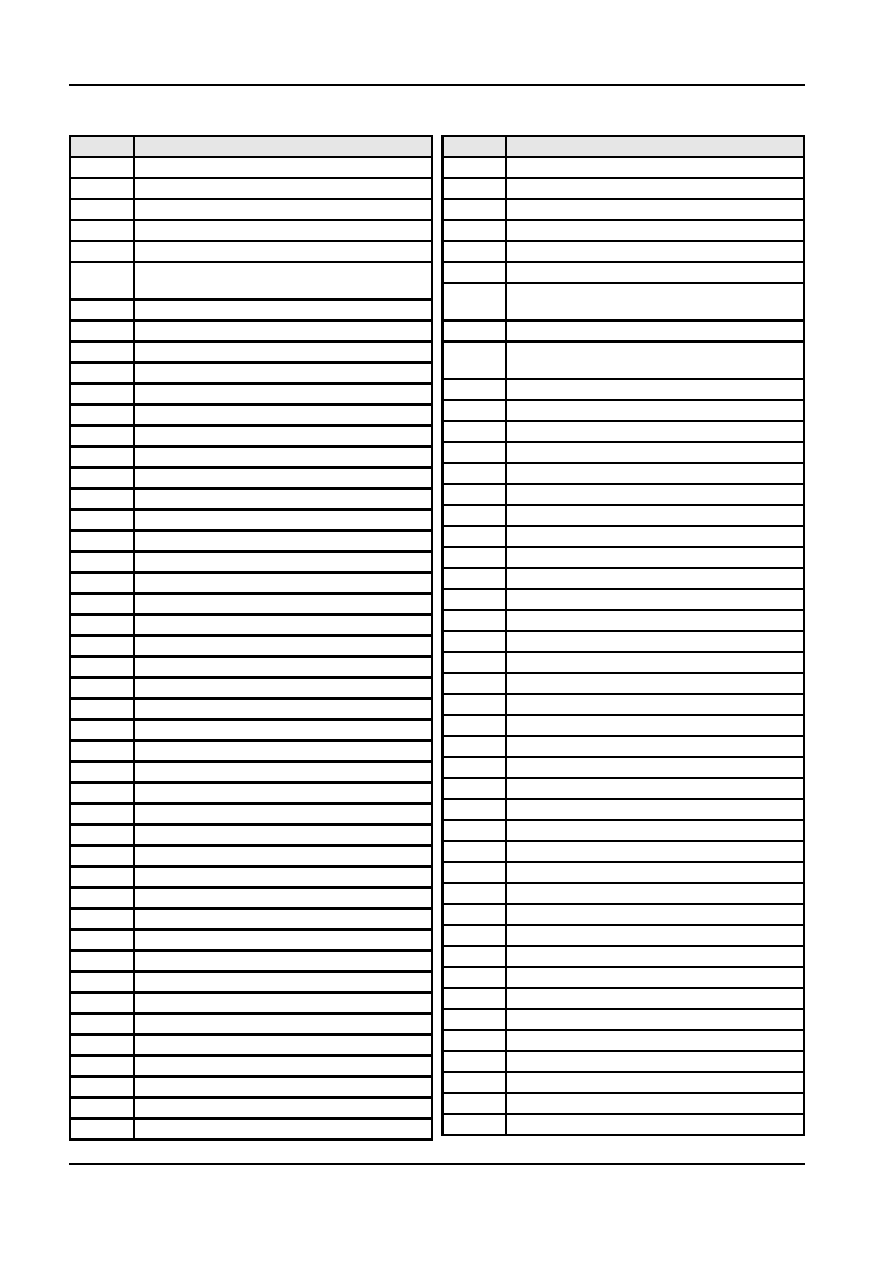
Item

Description

Item

Description

10

Harness, Plastic

56

Fork, Shift, 5th

11

Bolt

57

Insert

12

Gear – Driving

58

Rail Assy., Shift

13

Bushing – Extension Housing

59

Gear, 5th Speed Drive

14

Connector Lead

60

Ring, Snap

15

Transducer Assembly (for non ABS

61

Gear, Speedo (Non ABS vehicles only)

vehicles only)

62

Clip, Speedo Gear (Non ABS vehicles

16

O-Ring

only)

17

Retaining Clip

63

Bolt

18

Bolt

64

Flywheel Housing (contains input shaft

bearing retainer)

19

Extension, Bushing & Plate Assy.

65

Seal, Oil

20

Plate, Detent Guide

66

Shim

21

Plug, Cup

67

Bearing Assy., Input Shaft

22

Lever, Bonded Offset

68

Shaft, Input

23

Isolator cup

69

Cup

24

Ball

70

Taper Roller Bearing

25

Spring

71

Circlip

26

Seal, Oil

73

Gear, 5th Driving

27

Funnel, Oiling

74

Bearing Assy., Main Shaft Rear

28

Bolt

75

Gear, 1st Speed

29

Bolt, Alignment

76

Sleeve Assy., Bearing

30

Pin, Selector Arm

77

Bearing

31

Shaft, Shifter

78

Sleeve

32

Fork, Shift, 3-4

79

Ring Assy., Blocking

33

Fork, Shift, 1-2

80

Synchronizer Assy., 3rd-4th

34

Insert

81

Spring, Synchronizer

35

Arm Assy., Selector

82

Sleeve, Synchronizer

36

Plate, Interlock

83

Insert

37

Plate, Selector

84

Hub, Synchronizer

38

O-Ring

85

Gear, 3rd Speed

39

Plug

86

Bearing

40

Cover, Case

87

Spacer

41

Ring, Retaining

88

Ring, Snap

42

Pin, Pivot

89

Washer, Thrust

43

Switch, Back-Up

90

Gear, 2nd Speed

44

Bolt, Spring Anchor

91

Bearing, 2nd Speed

45

Lever, Shift, 5-R

92

Spacer

46

Ring, Snap

93

Shaft Assy., Output

47

Spacer, Rev. Cone

94

Ring, Spiral Retaining

48

Cone, Reverse

95

Washer, Thrust

49

Ring, Blocking

96

Cone, Inner

50

Synchronizer Assy., 5th

97

Race, Outer Cone

51

Spring, Synchronizer

98

Ring, 1-2 Blocking

52

Sleeve, Synchronizer

99

Spring

53

Insert

100

Gear, Reverse Sliding

54

Hub, Synchronize

101

Insert

55

Pin, Roll

G34501 en

308-03a-7 

Manual Transmission — I6 

308-03a-7

DESCRIPTION AND OPERATION (Continued)

Item

Description

102

Ball

103

Shaft and Hub Assy.

104

Spring

105

Fork, Pin & Roller Assy., Reverse

106

Bolt

107

Retainer, Rear

108

Shim

109

Pin, Roll

110

Shaft, Reverse Idler

111

Gear, Reverse Idler

112

O-Ring

113

Bearing Assy., Countershaft Rear

114

Bearing Assy., Countershaft Front

115

Gear, Countershaft

116

Case Assy., Transmission

117

Bush

118

Concentric Slave Cylinder & lines

119

Screw

120

Hose Clip

Reverse Brake

The reverse brake is applied through the 5th synchro

sleeve. This stops the rotation of the cluster gear

before the reverse idler is engaged eliminating gear

clash when the vehicle is stationary and reverse gear

is selected.
The spacer slides onto the cluster spline and rotates

with it. A snap ring holds the reverse brake

components in position. The tab on the reverse cone

locates into a recess in extension housing adjacent to

the lubrication funnel.
A shift interlock system, located in the cover prevents

engagement of more than one gear. The shift detent

is located in the extension housing turret and consists

of a detent plate, offset lever and spring loaded ball.

All gears except reverse are synchronized and helical

cut for smooth, crisp shifts and quiet operation.

Reverse is provided through a reverse idler gear

which slides along a shaft to engage spur gears on

the countershaft and output shaft. The case is

aluminium and all fasteners are metric.

G34501 en

308-03a-8 

Manual Transmission — I6 

308-03a-8

DIAGNOSIS AND TESTING

Gear rollover noise will disappear when the clutch is

Manual Transmission

disengaged or when the transmission is engaged in

gear. In the event that a transmission bearing is

Inspection and Verification

damaged, the noise is more pronounced while

engaged in gear under load or coast conditions than

NOTE: Gear rollover noise, inherent in manual

in NEUTRAL. When concerns of this nature are

transmissions, (caused by the constant mesh gears

encountered, it will be necessary to road test the

turning at engine idle speed while the clutch is

vehicle to determine if bearing noise exists. Under no

engaged and the transmission is in NEUTRAL), and

circumstances should any transmission rework be

clutch release bearing noise are sometimes mistaken

attempted to eliminate gear rollover noise, or clutch

for mainshaft bearing noise. Noise caused by a worn

release bearing noise.

or damaged clutch release bearing will be loudest

when the clutch is held disengaged.

Symptom Chart

Condition

Source

Action

  Remove transmission. If noise is

  Transmission Noisy in Gear

Lubricant level low or wrong type.

howling during start-up, check pilot
bushing. Check for loose flywheel and
housing alignment. Service or replace
as required. Refer to Section 308-01.

Transmission to flywheel housing and

  Fill to bottom of filler plug hold with

flywheel housing to engine block bolts

proper lubricant.

loose.

  Tighten bolts to 61-88 N-m (45-65

Pilot bushing worn or damaged.

lb-ft).

Improper transmission pilot

  Replace housing or input shaft bearing

retainer as required. Refer to Section

engagement into flywheel housing.

308-01.

Worn or damaged internal

  Disassemble transmission. Inspect

Input, output and countershaft

components.

bearings, gear and gear teeth for wear
and damage. Service or replace as
required.

Excessive amount of lubricant in

  Check level and type. Fill to bottom of

 Transmission 

Leaks

transmission–wrong type.

filler plug hole.

  Identify leaking fluid at engine, power

Other component(s) leaking.

steering and/or transmission.

  Remove all traces of lubricant on

False report.

exposed transmission surfaces. Check
vent for free breathing. Operate
transmission and Inspect for new
leakage. Service as required.

Worn or damaged Internal

  Remove transmission. Inspect for

leaks at the input shaft bearing retainer

components.

seal and gasket, shift rail expansion
plug top cover gasket. Inspect case for
sand holes. Service or replace as
required.

Inadequate thread sealant on threads.

  Apply sealant to bolt threads.

  Refer to Section 308-01 for clutch

  Transmission difficult to shift

Improper clutch release.

servicing procedures.

  Remove transmission and free up shift

Internal shift mechanism binding.

mechanism.

Synchronizer sleeve to hub fit.

  Remove and check for burrs or fit.

G34502 en

308-03a-9 

Manual Transmission — I6 

308-03a-9

DIAGNOSIS AND TESTING (Continued)

Condition

Source

Action

Binding condition between input shaft

  Check alignment and service as

and crankshaft pilot bearing.

required. Refer to Section 308-01.

  Drain and refill with specified fluid

Improper fluid.

(refer Specifications section).

  Gears Clash When Shifting from One

Engine idle speed too high.

  Adjust engine idle speed.

Forward Gear to Another

  Ensure complete clutch release. Refer

Improper clutch release.

to Section 308-01 for clutch servicing
procedures.

Binding condition between

  Remove transmission and replace pilot

transmission input shaft and crankshaft

bushing. Refer to Section 308-01.

pilot bushing.

Worn or damaged shifter forks,

  Service or replace as required.

synchronizer assembly, or gear clutch
teeth.

  Verify Jump-out with boot removed.

  Transmission Jumps Out of Gear

Stiff or improperly installed boot.

Replace boot if necessary.

Interference between shift handle and

  Adjust console to eliminate

console.

interference.

Transmission to engine mounting

  Tighten bolts to specification.

loose.

Flywheel housing to engine crankshaft

  Replace parts as required. Refer to

out of alignment.

Section 308-01.

Improper engagement between

  Replace parts as required. Refer to

transmission pilot and flywheel

Section 308-01.

housing.

  Replace pilot bearing. Refer to Section

Input shaft pilot bearing worn.

308-01.

Worn or damaged internal

  Check input and output shafts for

excessive end play, shift forks for

components.

loose mounting on shift rails, worn
pads, shift rail detent system for wear
or damage, synchronizer sliding sleeve
and gear clutch teeth for wear or
damage. Service or replace as
required.

  Transmission Will Not Shift Into One

Floor shift, interference between shift

  Adjust console or cut out floorpan to

Gear – All Other Gears OK

handle and console or floor cut out.

eliminate interference.

Restricted travel of internal shifter

  Remove transmission. Inspect shift rail

and fork system, synchronizer system

components.

and gear clutch teeth for restricted
travel. Service and replace as
required.

  Transmission is Locked in One Gear. It

Internal shifter components worn or

  Remove transmission. Inspect the

problem gear or gearshift rails and fork

Cannot be Shifted Out of that Gear

damaged.

and synchronizer for wear or damage.
Service or replace as required.

  Remove transmission. Replace

Selector arm finger broken.

selector arm assembly.

Bent shifter forks at pads and selector

  Service or replace as required.

slot.

  Transmission Will Not Shift Into

Worn or damaged internal

  Remove transmission. Check for

damaged reverse geartrain, misaligned

Reverse (All Others OK)

components.

reverse relay lever, shift rail and fork
system

G34502 en


Content   ..  259  260  261  262   ..