Ford Falcon. Manual - part 237
307-01-51 Automatic
Transmission 307-01-51
GENERAL PROCEDURES (Continued)
Gear shift cable adjustment
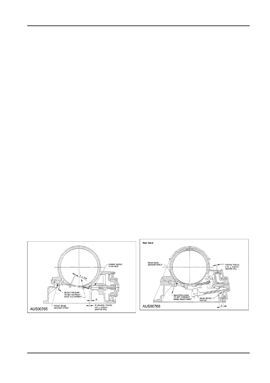
Rear Band
For more information, refer to Section 307-05.
1. Measure distance ‘A’ from the Rear Servo Piston
to the inner face of the Transmission Case using
Band adjustment
vernier calipers.
1. Apply air at 650/700 kPa to the Rear Servo
Front band
apply area (B2 outer).
1. Measure projection of Front Servo Push Rod from
2. Measure travel of the Piston, subtract 3.75mm
Transmission Case.
and divide the remainder by 2.5 to find Shim
1. Apply air at 650/700 kPa to the Front Servo
size.
apply area (B1 outer)
3.
Release
Air.
2. Measure travel of Push Rod and subtract
4. Fit Shim as per 2 below and re-check Piston
3mm to find Shim size.
travel is 3.75mm
± 0.625mm.
3.
Release
Air.
NOTE: A minimum of one Shim is required at
4. Fit Shim as per 2 below and re-check Push
all times - minimum Shim size is 1mm.
Rod travel is 3 mm
± 0.25mm.
2. Fit the Shim(s) selected to the shank of the
NOTE: A minimum of one Shim is required at
Anchor Strut as follows:
all times - minimum Shim size is 1 mm.
1. Inspect Shims for damage, wear or corrosion
2. Fit the Shim(s) selected to the shank of the
and replace as necessary.
Anchor Strut as follows:
2. Shims are to be installed between the Case
1. Inspect Shims for damage, wear or corrosion
abutment face and the Anchor Strut flange.
and replace as necessary.
3. Shim(s) are to be fitted by hand and under no
2. Shims are to be installed between the Case
circumstances to be hammered or forced.
abutment face and the Anchor Strut flange.
4. Shim(s) are to be pressed on by hand until an
3. Shim(s) are to be fitted by hand and under no
audible click is heard. The click indicates that
circumstances to be hammered or forced.
the Shim is clipped home correctly.
4. Shim(s) are to be pressed on by hand until an 3. The Shim thickness available are:
audible click is heard. The click indicates that
1.
1
mm
± 0.05, 2.0mm ± 0.07
the Shim is clipped home correctly.
2.
1.2mm
± 0.05, 2.2mm ± 0.08
3. The Shim thickness available are listed below:
3.
1.5mm
± 0.06, 2.4mm ± 0.08
1.
1
mm
± 0.05, 2.0mm ± 0.07
4.
1.8mm
± 0.07, 2.7mm ± 0.09
2.
1.2mm
± 0.05, 2.2mm ± 0.08
NOTE: All hardware must be correctly
3.
1.5mm
± 0.06, 2.4mm ± 0.08
installed and torqued to specification.
4.
1.8mm
± 0.07, 2.7mm ± 0.09
Rear Band Adjustment
Front Band Adjustment
Oil cooler flushing
When a clutch or band failure or other internal trouble
has occurred in the transmission, any metal particles
or clutch plate or band material that may have been
carried into the cooler should be removed from the
system by flushing the cooler and lines before the
G73098 en