Ford Falcon. Manual - part 51
205-02A-28
Rear Drive Axle / Differential — Beam Axle
205-02A-28
DISASSEMBLY AND ASSEMBLY (Continued)
3. To establish the thickness of the spacers
12. Remove the assembly from the carrier using the
required:- Total the thickness of the two spacers -
spreader. If the preload is correct, tie the selected
Add the gap measured with the feeler gauges.
spacers to the bearing cups to have them
Add 0.15 mm when using new bearings or 0.1
available for use in determining gear backlash. If
mm when using used bearings to preload the
correct preload is not obtained, a variation of
bearings.
0.025 mm on spacers will alter preload 8 N for
new bearings and approx. 4 N for used bearings.
4. Select two spacers, each half the thickness of the
Repeat steps 5-12.
value determined in Step 3.
5. Fit the carrier spreader adaptors and the spreader
Drive Pinion Position — Shim
to the carrier, together with a dial indicator
Selection
positioned over the carrier differential opening, as
close as possible to the centre line of the axle
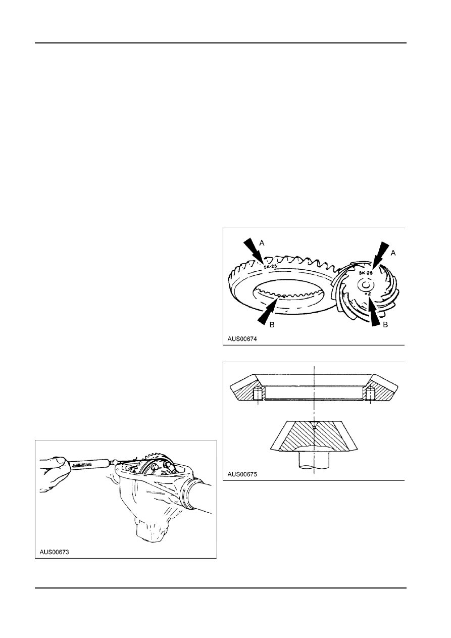
NOTE: The drive pinion and ring gear set
shafts. This may be done by using a pilot stud
identification marking (number 5K-25) is the matching
screwed into the side bearing lower stud hole,
number that appears on both the drive pinion and the
with the dial indicator plunger in contact with the
ring gear. When a new gear set is being installed in
opposite side of the carrier opening.
an axle, be sure that the same matching number
6. Use the spreader to expand the case until the
appears on both the drive pinion and the ring gear.
differential assembly with bearings and selected
spacers will fit into the carrier. A spread of 0.25 to
0.3 mm is usually sufficient. Under no
circumstances should the carrier be spread
more than 0.50 mm.
7. The differential assembly, with bearing cups and
selected spacers held against the bearing cones,
may now be fitted to the carrier, after removing
the dial indicator.
8. Release and remove the spreader tool leaving
adaptors in position.
9. Fit the bearing cups in their original positions,
tightening the bolts to 55 Nm torque.
10. Rotate the differential assembly at least six full
turns to seat the bearing rollers in the bearing
Pinion/Ring Gear Identification
cups.
11. Check the preload using a spring balance.
Measure the tension required to revolve the
assembly when a string is wrapped around the
differential case on the larger diameter, just
behind the drive gear. Balance readings must be
within the following limits: New bearings 25
± 10
N. Used bearings 13
± 5 N. These balance
readings are equivalent to the preload torques in
the Specifications.
NOTE: The ring gear and pinion are manufactured
within a tolerance of a specified distance. On the end
of each pinion, there is marked a plus (+) number, a
minus (-) number, or a zero (0) number which
indicates the best running position for each particular
gear set. This dimension is controlled by the
shimming behind the rear pinion bearing cup. When
the shim thickness is decreased, the pinion gear is
moved away from the ring gear. When the shim
thickness is increased, the pinion is moved closer to
the ring gear. A positive (+) number on the drive
G98788 en