Ford Falcon. Manual - part 44
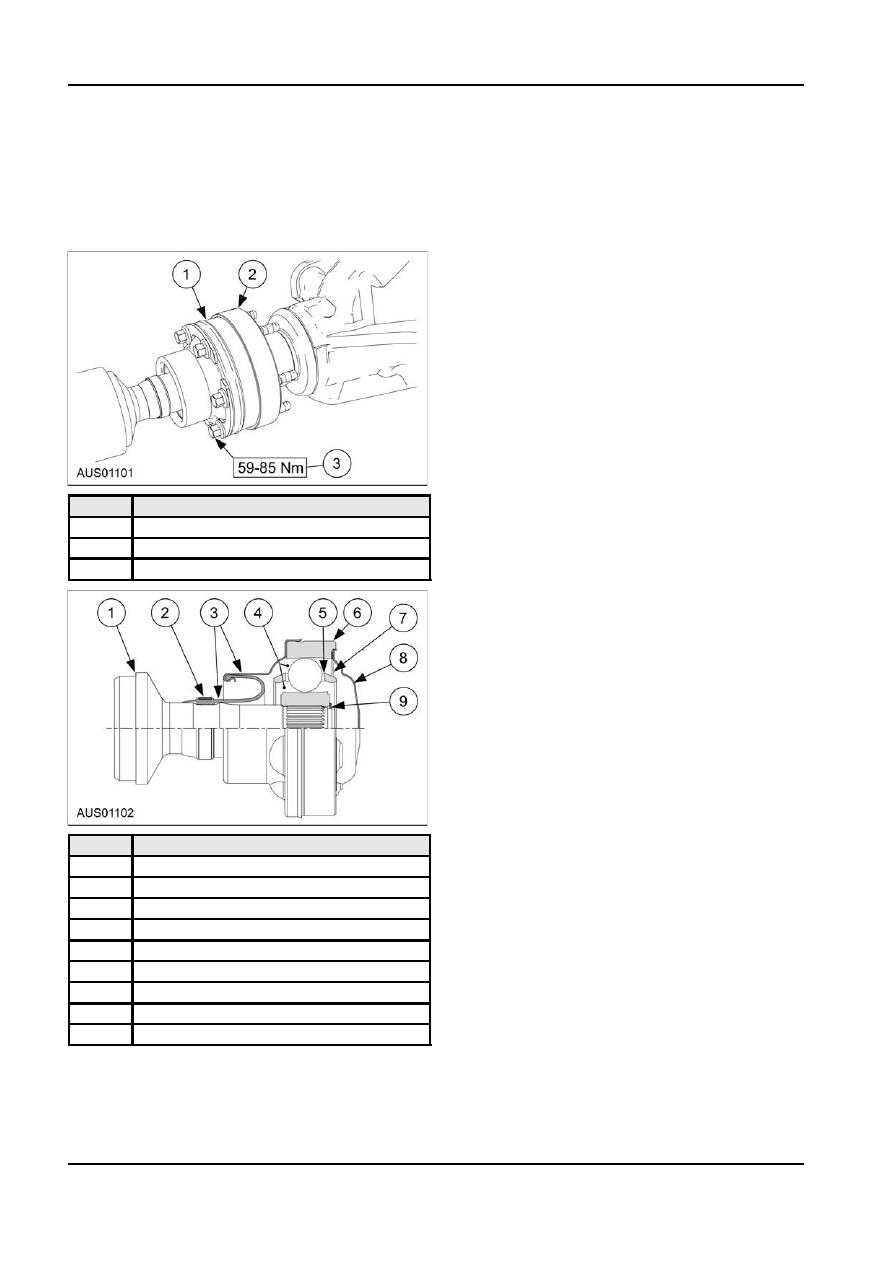
205-01-10 Driveshaft 205-01-10
DISASSEMBLY AND ASSEMBLY (Continued)
4. Using bearing puller (tool number ?) press CV
CV Joint Replacement
joint from shaft.
NOTE: To maintain balance mark all bolts and
5. Remove boot from shaft.
weights in reference to the companion flange.
Assembly
Disassembly
1. Inspect boot for damage and/or holes.
2. Take care whilst sliding boot onto stub shaft. A
small amount of CV joint grease may be used as
a lubricant.
3. Place metal sealing gasket inside boot can, keep
bolt holes aligned.
4. Press CV onto stub shaft using unique tool (tool
number ?), push on CV joint inner race. Ensure
double grooves on CV joint body are toward the
boot can.
5. Seat retainer circlip.
6. Pack joint with 60g of lubricant (supplied with CV
kit) throughout cage and races.
7. Seat CV boot can onto CV joint body, ensuring
bolt, and metal sealing gasket hole alignment, and
Item
Description
relieve any twist in the boot.
1
CV
8. Remove backing and place self-adhesive cork
gasket (supplied with CV kit) into stepped recess
2
Companion flange
on CV joint face, aligning bolt holes. Placing bolts
3
Bolt
through CV Joint as a guide to gasket alignment.
Gasket alignment is critical to sealing integrity.
9. Seat rear can onto CV again ensuring bolt holes
are aligned.
10. Clamp boot in location as shown in figure.
11. Bolts to be torqued to 72Nm (+/- 13Nm). Opposite
bolts to be torqued until all reach spec.
Item
Description
1
Stub Shaft
2
Boot Clamp
3
Boot Asy
4
Grease
5
Steel Gasket
6
CV Joint Asy
7
Cork Gasket
8
Circlip
9
Grease Cover
1. Follow steps to remove drive shaft.
2. Remove end cap from CV joint, grease can and
remove retaining clip.
3. Using a hammer and soft punch remove the boot
can forwards from the CV joint.
G96429 en