Ford Falcon. Manual - part 43
 

  Index      Ford     Ford Falcon - service repair manual 2002-2005 year


Search            


Content   ..  41  42  43  44   ..


Ford Falcon. Manual - part 43


205-01-6 Driveshaft 205-01-6

GENERAL PROCEDURES

UJ Side view Angle (in

Actual shim required

Take — Off Shudder

degrees) (front shaft

(mm)

NOTE: Take off shudder is characterised by a

angle - rear shaft angle)

driveline vibration (felt in the driver / passenger seats),

-1.9

°

5

which peaks and abates between 15 - 25kph under

-1.8

°

4

heavy throttle applications. It is due to the

-1.7

°

4

misalignment of the centre bearing bracket in the ’Z’

(vertically) direction.

-1.6

° (Optimal U/J angle)

3

-1.5

°

3

1.  To eliminate take off shudder, follow the steps

outlined below:

-1.4

°

2

Check engine/transmission/diff mounts for

-1.3

°

2

condition and correct location. If OK then

-1.2

°

1

proceed to next step.

-1.1

°

1

With vehicle on hoist, remove existing shims

-1.0

°

0

(if any) and re-torque bolts up to the floor brkt

-0.9

°

0

mounting surface.
Using an Inclinometer, take the front and rear

shaft angles.
NOTE: Use the same inclinometer in the

same orientation for each shaft, failing to do

this will result in inaccurate measurements.

Determine the resultant angle by subtracting

the front shaft angle from the rear shaft angle

(ie front shaft angle - rear shaft angle).
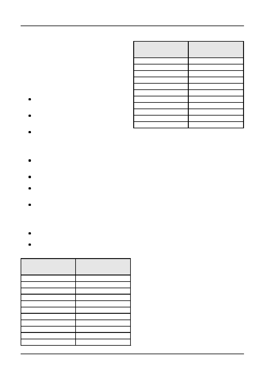
Use look-up table below to determine shim

size required.
Loosen CB bolts, and assemble correct

determined shims, re-torque bolts to 36Nm

(

±7Nm).

Using an Inclinometer, take the front and rear

shaft angles.
NOTE: Use the same inclinometer in the

same orientation for each shaft, failing to do

this will result in inaccurate measurements.

Check if front and rear resultant angle is at

the optimal figure (-1.6

°).

Take vehicle for short run on safe roads and

do two WOT runs to 25kph to verify fix.

UJ Side view Angle (in

Actual shim required

degrees) (front shaft

(mm)

angle - rear shaft angle)

-3.0

10

-2.9

10

-2.8

9

-2.7

9

-2.6

°

8

-2.5

°

8

-2.4

°

7

-2.3

°

7

-2.2

°

6

-2.1

°

6

-2.0

°

5

G96424 en

205-01-7 Driveshaft 205-01-7

REMOVAL AND INSTALLATION

Installation

Driveshaft Assembly

1.  If the seal installed on the end of the transmission

NOTE: If assembling or disassembling any part of the

extension housing is damaged in any way, install

driveshaft asy then either a driveshaft or system

a new seal.

re-balance is recommended.

2.  Lubricate the slip spline with transmission

lubricant. Install the slip spline on the transmission

NOTE: Before disassembly mark location (and

output shaft.

weight) of clip on balance weights (if fitted).

3.  Match the alignment marks and locate the CV

Re-assemble in original position.

joint, bolts and balance weights to the companion

NOTE: Before disassembly check if Centre Bearing

flange and CV bolts. Torque 72Nm (+/- 13Nm).

shims are present and retain for re-assembly.

4.  Locate the center bearing bracket on the body.

Torque to 36Nm (+/- 7Nm).

NOTE: The driveshaft rear CV and the pinion flange

of the axle have yellow paint alignment marks that are

assembled as close together as possible. If these are

not visible, mark the CV and the flange so that they

may be installed in their original positions.

Removal

Item

Description

1

Flex

2

Driveshaft

3

Centre bearing assembly

4

Universal joint

5

Driveshaft

6

CV assembly

7

Differential assembly

8

Bolt

9

transmission assembly

1.  Locate Jack or transmission stand at centre

bearing to support before removal.

2.  Disconnect the rear CV joint from the pinion

flange.

3.  Disconnect the Centre-Bearing closing bracket

from the body. Pull the driveshaft toward the rear

of the vehicle until the front Flex Coupling slip

spline clears the transmission extension housing

and the seal.
NOTE: To prevent oil loss and ingress of foreign

material plug the extension housing with a

mainshaft dust cover or slip flange.

G96425 en

205-01-8 Driveshaft 205-01-8

DISASSEMBLY AND ASSEMBLY

Flex Joint Replacement

Universal Joint Replacement

Disassembly and Assembly

NOTE: Procedure can be used for single piece slip

yoke/tube yoke removal as well.

NOTE: To maintain driveline balance, mark the slip

flange in relation to the Driveshaft so that they may be

External Clip Type U-Joint

installed in their original positions.

NOTE: The arrows molded into the flex coupling must

always be pointing to the slip or tube flange arms.

Otherwise premature failure of the component will

occur.

Item

Description

1

Driveshaft

2

Slip yolk assembly

3

Snap ring

4

Bearing

1.  Remove the retaining bolts from the flex joint to

shaft and flex joint to slip flange.

5

Driveshaft

2.  Replace flexible coupling, ensuring arrows

6

U-joint assembly

(moulded in flex rubber) are pointing to the slip or

7

Nut

tube flange arms and locate spigot to shaft.

Reinstall new nuts and bolts (from service kit) and

Disassembly

Torque to 77 Nm.

NOTE: To maintain drive line balance, mark the

NOTE: If there is any damage to alignment bush

relation of the slip yoke and the pinion flange on the

on slip flange then replace slip flange.

axle, with the shaft so that they may be installed in

their original positions.

1.  Remove the clips that retain the bearings in the

yoke. Apply penetrating oil to the bearing cups to

assist removal if required.

2.  Using a “G” clamp and suitable adaptors, or

similar equipment, press on one of the bearing

cups so as to drive the opposite bearing from the

yoke.
NOTE: All hardware must be correctly installed

and torqued to specification.

G96426 en

205-01-9 Driveshaft 205-01-9

DISASSEMBLY AND ASSEMBLY (Continued)

3.  Remove the bearing from the spider, rotate the

Centre Bearing Replacement

shaft 180

° and remove the second bearing.

Detach the yoke from the shaft.

NOTE: To maintain driveline balance, mark the

relation of the Universal joint end yoke to front and

rear shafts so that they may be installed in their

original position.

NOTE: Do not use impact/rattle gun on centre bearing

bolts as you will run the risk of stripping the thread in

the nut located inside the body.

NOTE: It is important to keep and replace original CB

shims.

Disassembly and Assembly

4.  Repeat this procedure to remove the bearings

from the yoke and rear of the shaft.

Assembly
1.  Position the spider in the yoke. Lift the spider to

one side of the yoke and locate a bearing cup on

the spider. While holding the spider in the bearing

press the bearing into the yoke until the clip can

be installed on the bearing. Install the clip.

2.  Rotate the yoke 180

° and install the other bearing

while holding the spider into the bearing to

prevent the needle rollers from being dislodged.

Item

Description

The bearing cups are fitted with plastic pads that

impart a preload on the ends of the spider. These

1

Shims

pads must be compressed by use of a “G” clamp

2

Centre bearing bracket assembly

or vice. Tap the yoke to seat the clip previously

3

Bolt

fitted and install the remaining clip.

1.  Remove Universal joint as directed.

3.  Repeat this procedure to install the remaining

bearings in the shaft.

2.  Remove locking nut retaining end yoke flange to

drive shaft, press off end yoke from front shaft.

3.  Press Centre Bearing from shaft and Replace.
4.  Press fit end yoke and new lock nut and torque to

157Nm (+/- 20Nm).
NOTE: Careful not to apply force to other race of

bearing.

G96428 en


Content   ..  41  42  43  44   ..