Ford Falcon. Manual - part 38
 

  Index      Ford     Ford Falcon - service repair manual 2002-2005 year


Search            


Content   ..  36  37  38  39   ..


Ford Falcon. Manual - part 38


204-04-5 

Wheels and Tyres 

204-04-5

DIAGNOSIS AND TESTING (Continued)

3.  Rotate the two front tyres back to their original

5.  Road test the vehicle. If the drift is corrected,

position.

install a new rear tyre. If the drift remains, install a

new front tyre on the opposite side of the vehicle.

4.  Rotate one of the front tyres with its

corresponding rear tyre on the same side of the

vehicle.

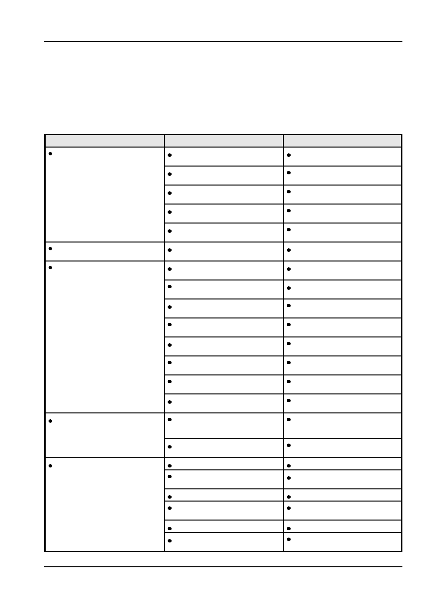
Symptom Chart

Condition

Source

Action

  Tyres show excess wear on edge of

Underinflated tyres.

  ADJUST the tyre pressure.

tread

  RETURN vehicle —NOTIFY the

Vehicle overloaded.

customer of overload condition.

  SET the alignment to specification.

Incorrect wheel alignment.

REFER to Section 204-00.

  RETURN vehicle — NOTIFY the

High-speed cornering.

customer of cause of condition.

  ADVISE the customer of intervals.

Incorrect tyre rotation

condition. ROTATE tyres.

  Tyres show excess wear in center of

Overinflated tyres.

  ADJUST the tyre pressure.

tread

  Other excessive/uneven tyre wear

Improper tyre pressure.

  ADJUST the tyre pressure.

problems

Worn or damaged suspension

 REFER 

to 

Section 

204-00.

components.

  INSTALL the correct tyre and wheel

Incorrect tyre/wheel usage.

combination.

Damaged, loose, or leaking shock

  TIGHTEN or INSTALL new shock

absorbers or struts.

absorbers as necessary.

  SET to specification. REFER to

Incorrect wheel alignment.

Section 204-00.

Wheel and tyre assembly out of

  BALANCE the wheel and tyre

balance.

assembly.

Excessive lateral or radial runout of

  REFER to Component Tests in this

wheel or tyre.

section.

  ADVISE the customer of the condition.

Tyres need rotating.

ROTATE the tyres.

Incorrect application or mismatched

  FOLLOW the manufacturer’s

  Wheel mounting is difficult

parts, including lug bolts and wheel

specifications.

nuts.

  CLEAN or INSTALL new parts as

Corroded, worn or damaged parts.

necessary.

  Wobble or shimmy

Worn or damaged wheel bearings.

 REFER 

to 

Section 

204-00.

Loose or damaged suspension

 REFER 

to 

Section 

204-00.

components.

Bent or damaged wheel.

  INSTALL a new wheel as necessary.

Wheel and tyre assembly out of

  BALANCE the wheel and tyre

balance.

assembly.

Damaged tyre.

  INSTALL a new tyre as necessary.

  TIGHTEN to specification. Refer to

Loose wheel nuts.

Wheel and Tyre in this section.

G43322 en

204-04-6 

Wheels and Tyres 

204-04-6

DIAGNOSIS AND TESTING (Continued)

Condition

Source

Action

 Vehicle 

vibrations

Driveline.

 REFER 

to 

Section 

100-04.

Wheel and tyre assembly out of
balance.

Wheel hub face/pilot/bolt circle runout.

 High-speed 

shake

 REFER 

to 

Section 

100-04.

Wheel and tyre assembly out of
balance.
Damaged or worn wheel bearings.
Damaged or worn suspension/steering
linkage.
Driveline.
Brake discs/imbalance.

  INSTALL new wheel nuts. Refer to

  Damaged wheel nuts

Loose wheel assembly.

Wheel and Tyre in this section.

  REMOVE the wheel nuts. INSPECT

Overtightened wheel nuts.

for damage. INSTALL new
components as necessary. Refer to
Wheel and Tyre in this section.

  If the corrosion is slight, BRUSH away

  Frozen wheel nuts

Corrosion or galling.

the corrosion with a wire brush. If the
corrosion is excessive, INSTALL new
wheel studs and wheel nuts. REFER
to Section 204-01 (front) or Section
204-02 (rear). If the condition persists,
LUBRICATE the first three threads of
each wheel stud with a graphite-based
lubricant

 CAUTION: Do not allow the

lubricant to get on the cone

seats of the stud holes or on the

cone angles of the wheel nuts.

Overloading.

  REDUCE the load weight.

Tyre Runout

Component Tests

Measure radial and lateral runout at the positions

Tyre and Wheel Runout

shown in the illustration. Runout should not exceed

Before checking runout, and to avoid false readings

specifications.

caused by temporary flat spots in the tyres, check

runout only after the vehicle has been driven far

enough to warm the tyres.
Excessive radial and lateral runout of a wheel and tyre

assembly can cause roughness, vibration, wheel

tramp, tyre wear, and steering wheel tremor.
The extent of the runout is measured with a radial

runout gauge. All measurements are made on the

vehicle with the tyres inflated to recommended

inflation pressures.

Wheel Runout

Measure radial and lateral wheel runout at the

positions shown on the illustration. Runout should not

exceed specifications. Note that the tyre has been

removed.

G43322 en

204-04-7 

Wheels and Tyres 

204-04-7

DIAGNOSIS AND TESTING (Continued)

G43322 en

204-04-8 

Wheels and Tyres 

204-04-8

GENERAL PROCEDURES

Straightening Wheels, Rims or

Components

NOTE: Do not heat wheels in an attempt to soften

them for straightening to repair damage. The special

alloy used in these wheels is heat-treated.

Uncontrolled heating from welding affects the

properties of the material.
Do not weld the wheels for any reason.

Wheel and Tyre Assembly Balancing

1.  Wheel and tyre assemblies should be dynamically

balanced. The wheel centre should be mounted

and located on a 70.45 to 70.50 mm diameter

spigot and clamped against the mounting plate via

the wheel stud holes, (i.e. as on a vehicle).

2.  When balancing wheels note that the weights are

different on alloy and steel wheels.

3.  Clip-on weights are to be used where the wheel

has a lip on the flange to accept a clip-on weight,

otherwise stick-on weights are to be used. For

stick on weights, the thickness of the lead weight

plus the adhesive should not exceed 4.5mm.
NOTE: It is important that only the correct balance

weights are used.

Item

Description

1

Steel wheel weights

2

Aluminium wheel weights

G43323 en


Content   ..  36  37  38  39   ..