Ford Ranger EV. Electric Manual - part 12
 

  Index      Ford     Ford Ranger EV - Electric manual 1998 year


Search            


Content   ..  10  11  12  13   ..


Ford Ranger EV. Electric Manual - part 12


LESSON 1: VEHICLE OVERVIEW

1-45

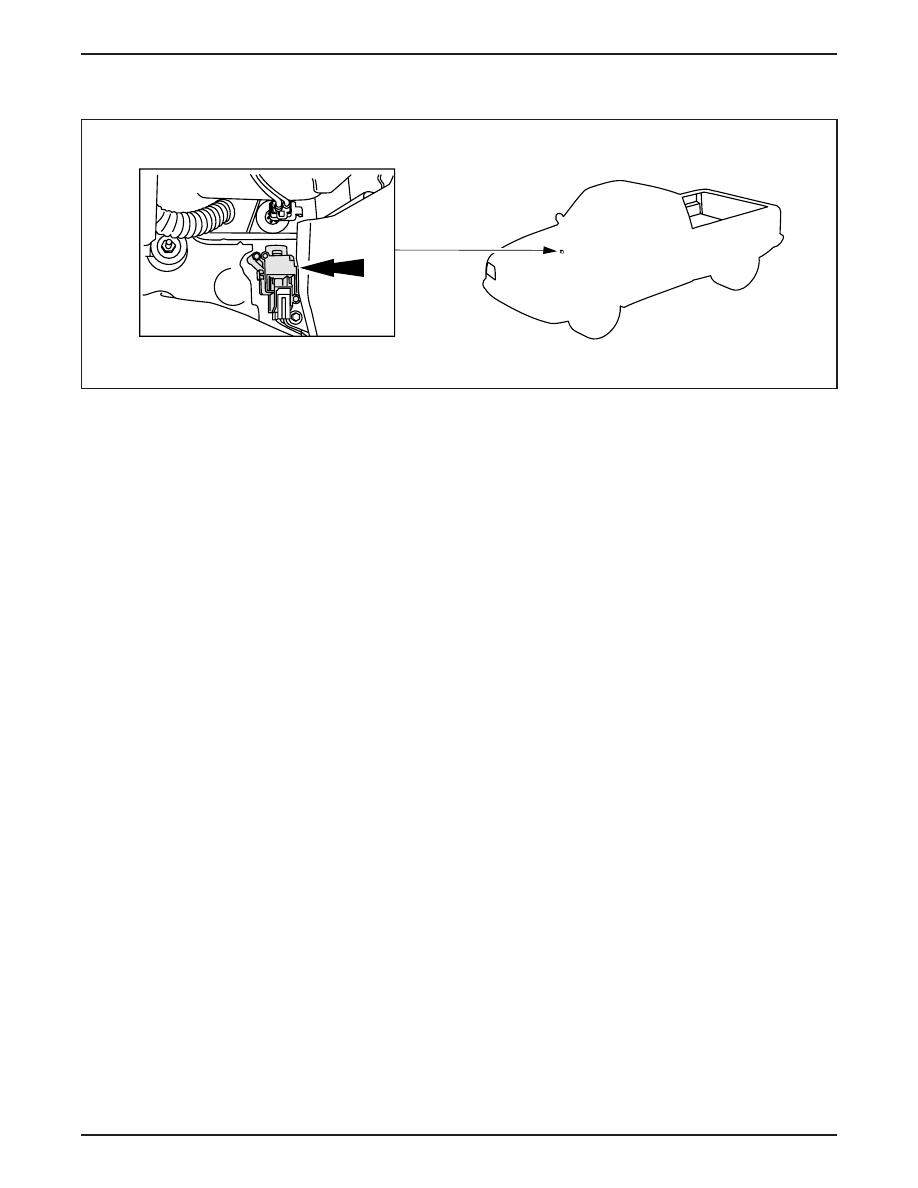
INERTIA SHUTOFF SWITCH

ER031-A

Inertia Shutoff Switch Location

The inertia shutoff switch (arrow) is located above the carpet line

and below the evaporator assembly on the passenger side of the

vehicle.

The inertia shutoff switch on the Electric Ranger performs a similar

function as the inertia shutoff switch on the gasoline-powered

Ranger.

– On both vehicles, the inertia shutoff switch disables the vehicle

powertrain in the case of an accident.

– On the gasoline-powered Ranger, the inertia shutoff switch

disables the fuel pump.

– On the Electric Ranger, the inertia shutoff switch interrupts the

high voltage power to the vehicle systems.

The POWER RESET lamp illuminates whenever the inertia shutoff

switch is triggered.

– The reset button is located on top of the inertia shutoff switch.

Emergency Power Off (EPO)

The EPO is a fail-safe system designed to safeguard against

personal injury and prevent vehicle damage.

EPO is activated when the inertia shutoff switch is triggered or a

high voltage interlock is disconnected.

– An EPO signal is sent to disable all high voltage loads and shut

down the vehicle.

– TIM, BCM, and IAA can initiate an EPO signal.

LESSON 1: VEHICLE OVERVIEW

1-46

CURRENT LEAKAGE DETECTION

Current Leakage Detection

The Electric Ranger uses a current leakage detection system to

monitor the integrity of the electrical system.

The BCM monitors the high voltage system for current leakage by

checking the DC circuitry for a low impedance path.

Current leakage detection is performed by relays, leakage current

shunts and current limiting resistors within the BCM.

This internal circuitry interfaces with either terminal of the traction

battery to measure impedance path between the terminal and the

vehicle chassis.

If the BCM detects severe leakage, the electric hazard warning

lamp in the instrument cluster will illuminate.

NOTE: If the electric hazard warning lamp remains illuminated after

lamp prove out, service the vehicle.

LESSON 1: VEHICLE OVERVIEW

1-47

SUSPENSION SYSTEM

Rear Suspension Components

The rear suspension system is designed specifically for the Electric

Ranger.

The DeDion rear axle (B) consists of:

– a thick-walled aluminum tube.

– sand-cast aluminum ends with Bearing carriers and spring seats.

– aluminum ends that are welded to the aluminum tube.

The rear axle utilizes a Watts linkage (A) for handling and control.

The rear shock absorbers and jounce bumper brackets are unique.

Composite single-rate leaf springs are used for weight reduction.

Carryover Ranger spring mounts and shackles are used.

Front Suspension System

The front suspension consists of Ranger 4x4 control arms and

modified Explorer 4x2 steering knuckle and spindle assemblies.

A unique stabilizer bar is tuned for proper roll stiffness.

Unique torsion bars and shock absorbers attach to carryover

Ranger mounts.

LESSON 1: VEHICLE OVERVIEW

1-48

TRACTION BATTERY CHARGING COMPONENTS

Power Control Station (PCS)

Power Control Station (PCS)

The Electric Ranger’s traction battery is charged by an off-board

power control station (PCS).

The PCS requires 240-volt 40 amp AC service.

When connection is made from the PCS to the vehicle:

– self test and vehicle confirmation tests are initiated.

– if the system is operational, the green charging light will

illuminate on the PCS.

– the green charging light indicates the self test and the vehicle

confirmation tests are compete and charging has begun.

– the charger fans will start cooling the on-vehicle charger

approximately four minutes after the charging light illuminates

steadily.

ER036-A


Content   ..  10  11  12  13   ..