Ford Ranger EV. Electric Manual - part 4
 

  Index      Ford     Ford Ranger EV - Electric manual 1998 year


Search            


Content   ..  1  2  3  4  5  ..


Ford Ranger EV. Electric Manual - part 4


LESSON 1: VEHICLE OVERVIEW

1-13

Battery Control Module (BCM)

Battery Control Module (BCM)

The battery control module (BCM) (arrow) is located in the upper

front section of the traction battery.

The BCM is a high and low voltage module that controls all battery

system operations.

The BCM monitors the temperature and state of charge of the

39 battery modules in the traction battery.

The BCM controls battery charging and cooling.

The BCM controls the optional battery heating system operation

if equipped.

LESSON 1: VEHICLE OVERVIEW

1-14

INPUTS

BATTERY

CONTROL

MODULE

(BCM)

OUTPUTS

Battery Temperature
Sensor 1-4

Emergency Power Off
(EPO)

Battery Voltage
Sensors

Battery Pack State
Of Charge (SOC)

Digital Transmission 
Range (DTR) Sensor

Charge Cord Plugged
In Signal

High Voltage Power
Distribution Box (HVDB)

Emergency Power Off
(EPO)

Battery Heaters

Battery Charger

Battery Pack Cooling 
Fan

Charger Contactor 
Relay

Negative Contactor
Relay

LESSON 1: VEHICLE OVERVIEW

1-15

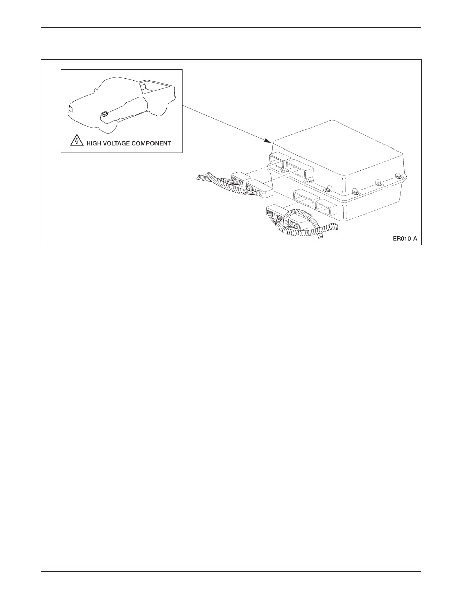
TRACTION INVERTER MODULE (TIM)

Traction Inverter Module (TIM)

The traction inverter module (TIM) (arrow) is located underneath

the center rear of the vehicle.

The TIM is a high and low voltage module that performs two

functions:

– vehicle powertrain control

– electric current conversion for the motor/transaxle

The TIM controls the vehicle powertrain by processing driver,

module, and sensor inputs, and calculating a motor torque

command.

The TIM converts high voltage DC from the traction battery into

three phase AC used by the motor/transaxle.

The TIM consists of:

– three high power, high-speed insulated gate bipolar transistor

modules (IGBTs).

– four large filter capacitors (used during precharging functions).

– two-phase current sensors.

– a high-performance microcontroller.

– logic circuitry and control circuits.

ER011-A

HIGH VOLTAGE COMPONENT

LESSON 1: VEHICLE OVERVIEW

1-16

The IGBTs are used to switch on and off the three motor phases.

– As they switch on and off, the IGBTs produce voltage spikes

that have the potential to damage the TIM.

– Capacitors are used as a filters to protect the TIM and maintain

traction bus voltage during IGBT switching.

– These capacitors retain traction battery voltage and provide

current capability for instantaneous torque.

NOTE: The TIM is equipped with a bleed down system which

ensures that the capacitors are discharged to less than 50 volts within

two minutes after the driver’s key is turned to the OFF position.

Be sure to allow for capacitor bleed down time before attempting

maintenance or repair.

INPUTS

TRACTION

INVERTER

MODULE

(TIM)

OUTPUTS

Motor Temperature
Sensor

Emergency Power Off
(EPO)

Accelerator Pedal
Sensors 1-3

Brake Pedal Sensor

Digital Transmission
Range (DTR) Sensor

Charge Cord Plugged 
In Signal

Anti-Lock Brake 
Module

Oil Pressure Sensor

Vehicle Speed Signal

Emergency Power Off
(EPO)

Precharge Contactor
Relay

Main Contactor Relay

Electric Motor/
Transaxle

Oil Pump Relay


Content   ..  1  2  3  4  5  ..