Ford Focus RS (2011 year). Instruction - part 99
DETAILS/RESULTS/ACTIONS
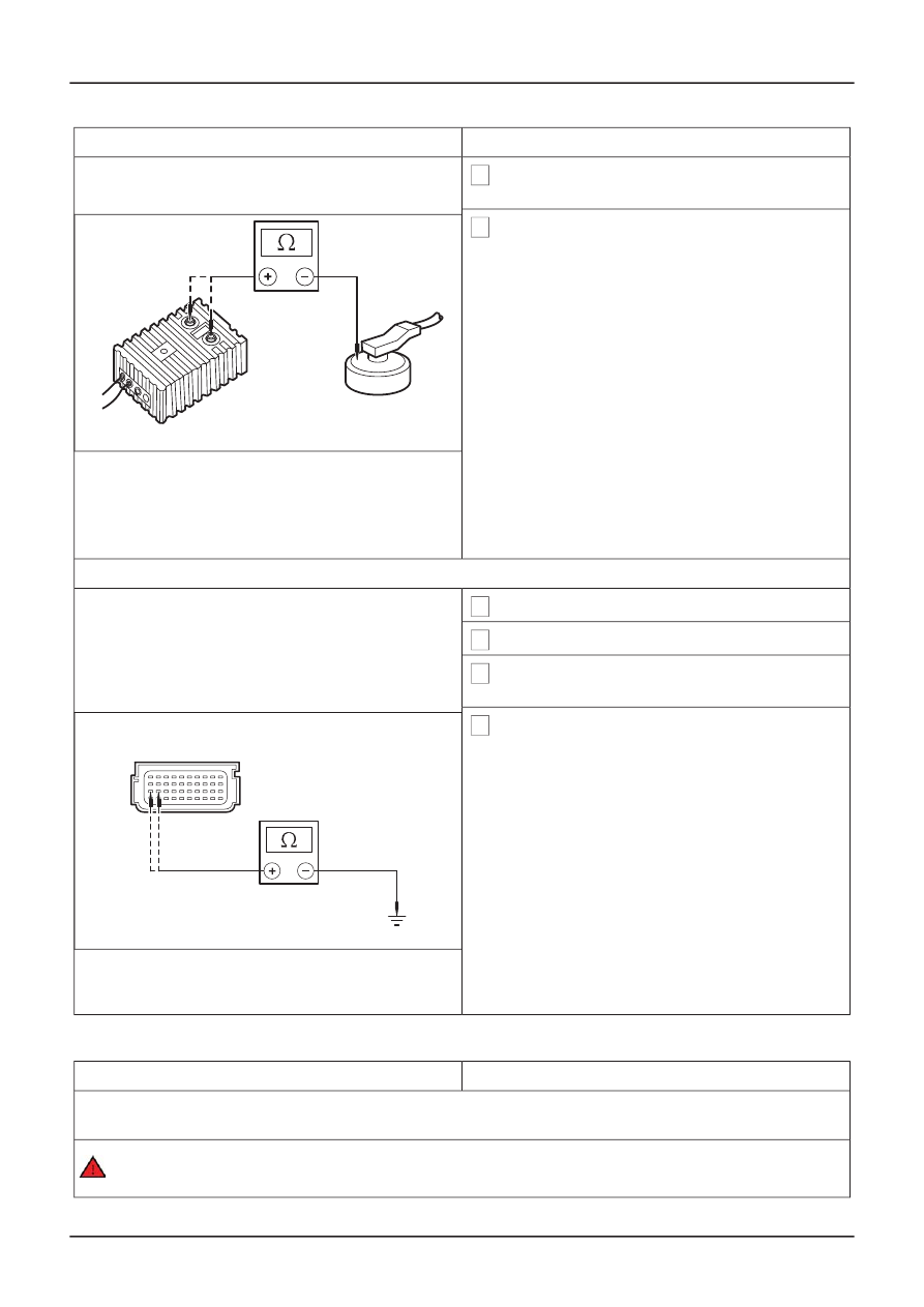
TEST CONDITIONS
3 Connect the test and deployment lead to the
Ford approved diagnostic tool.
4 Measure the resistance between each of the
terminals and the passenger side air curtain
module casing.
• Are the resistances greater than 10,000 ohms?
ൺ
Yes
E39389
REPEAT the self-test, CLEAR the DTCs.
REACTIVATE the system.
ൺ
No
INSTALL a new passenger side air curtain
module. REFER to: (501-20 Supplemental
Restraint System)
REPEAT the self-test, CLEAR the DTCs.
REACTIVATE the system.
1 Ignition switch in position 0.
2 Disconnect RCM C429.
3 Disconnect Passenger Side Air Curtain Module
Simulator.
4 Measure the resistance between the:
• RCM C429 pin 11, circuit 91S- JA51 (BK/BU),
harness side and ground.
• RCM C429 pin 12, circuit 15S-JA51 (GN/BU),
harness side and ground.
TIE0036515
• Are the resistances greater than 10,000 ohms?
ൺ
Yes
REPEAT the self-test, CLEAR the DTCs.
REACTIVATE the system.
ൺ
No
REPAIR circuit 15S-JA51 (GN/BU) or circuit
91S-JA51 (BK/BU). REPEAT the self-test,
CLEAR the DTCs. REACTIVATE the system.
PINPOINT TEST BD : DTC B2780: PASSENGER SIDE AIR CURTAIN CIRCUIT SHORT TO BATTERY
DETAILS/RESULTS/ACTIONS
TEST CONDITIONS
BD1: CHECK THE PASSENGER SIDE AIR CURTAIN WIRING HARNESS FOR A SHORT TO
BATTERY OR IGNITION
WARNING: To avoid accidental deployment, the RCM backup power supply must be depleted.
Wait at least one minute after disconnecting the battery ground cable(s) before commencing
G401865en
501-20B-
96
Supplemental Restraint System
501-20B-
96
DIAGNOSIS AND TESTING
Side Air Curtain Module - Vehicles Built From
:
22-06-2007
(Removal and Installation),
BC3: CHECK THE PASSENGER SIDE AIR CURTAIN WIRING HARNESS FOR A SHORT TO GROUND