Ford Focus RS (2011 year). Instruction - part 72


  Index      Ford     Ford Focus RS - service repair manual (2011 year) in english


Search            


Content   ..  70  71  72  73   ..


Ford Focus RS (2011 year). Instruction - part 72


DETAILS/RESULTS/ACTIONS

TEST CONDITIONS

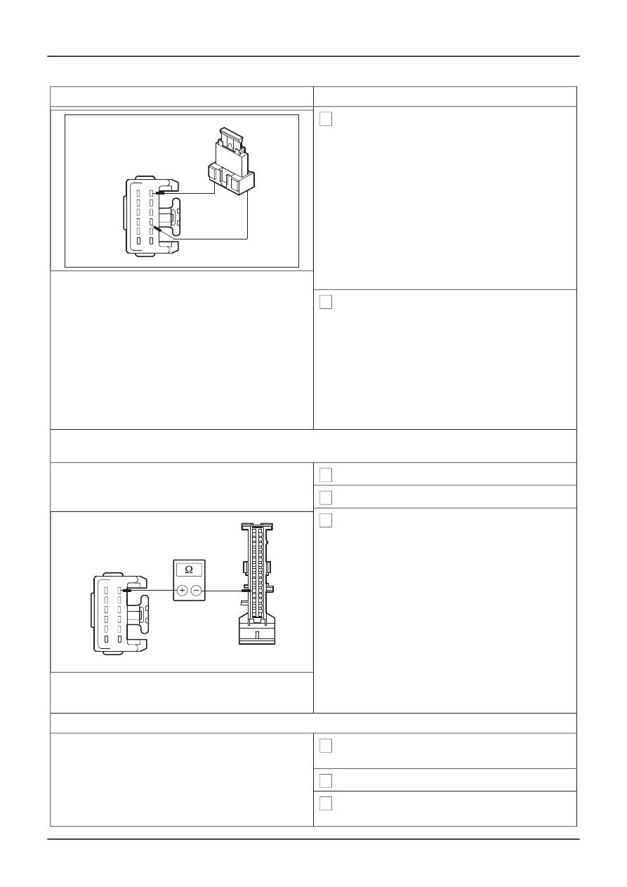
3 Connect a fused jumper wire (10 A) at the

wash/wipe system switch, connector C441, pin
6, circuit 91S-KA10 (BK/GN) and pin 3, circuit
91-KA12 (BK/WH), wiring harness side.

VFE48138

4 Ignition switch in position II.

• Do the windshield wipers operate at slow

speed?

Yes

RENEW the wash/wipe system switch.
CHECK the operation of the system.

No

GO to D7.

D7: CHECK CIRCUIT 91S-KA10 (BK/GN) BETWEEN WASH/WIPE SWITCH AND CENTRAL
JUNCTION BOX (CJB) FOR BREAKS

1 Ignition switch in position 0.

2 Disconnect CJB from connector C103.

3 Measure the resistance between the wash/wipe

system switch, connector C441, pin 6, circuit
91S-KA10 (BK/GN), wiring harness side and
the CJB, connector C103, pin 21, circuit 91S-
KA10 (BK/GN), wiring harness side.

• Is a resistance of less than 2 Ohms registered?

Yes

VFE0038556

GO to D8.

No

LOCATE and RECTIFY the break in the circuit
between the wash/wipe system switch and
CJB using the Wiring Diagrams. CHECK the
operation of the system.

D8: CHECK VOLTAGE AT THE WINDSHIELD WIPER MOTOR

1 Connect Wash/wipe system switch to connector

C441.

2 Connect CJB to connector C103.

3 Disconnect windshield wiper motor from

connector C848.

G401883en

501-16-

26

Wipers and Washers

501-16-

26

DIAGNOSIS AND TESTING

DETAILS/RESULTS/ACTIONS

TEST CONDITIONS

4 SWITCH ON slow wipe speed.

5 Ignition switch in position II.

6 Measure the voltage between the front wind-

screen wiper motor, connector C848, pin 2,
circuit 32-KA10 (WH/GN), wiring harness side
and ground.

• Does the meter display battery voltage?

Yes

VFE0038543

RENEW the windshield wiper motor. CHECK
the operation of the system.

No

GO to D9.

D9: CHECK CIRCUIT 32-KA10 (WH/GN) BETWEEN CENTRAL JUNCTION BOX (CJB) AND FRONT
WIPER MOTOR FOR BREAKS

1 Ignition switch in position 0.

2 Disconnect CJB from connector C96.

3 Measure the resistance between the front

windscreen wiper motor, connector C848, pin
2, circuit 32-KA10 (WH/GN), wiring harness side
and the CJB, connector C96, pin 41, circuit 32-
KA10 (WH/GN), wiring harness side.

• Is a resistance of less than 2 Ohms registered?

Yes

VFE0038557

INSTALL a new GEM. CHECK the operation
of the system.

No

LOCATE and RECTIFY the break in the circuit
between CJB and the windshield wiper motor
using the Wiring Diagrams. CHECK the oper-
ation of the system.

PINPOINT TEST E : INTERMITTENT WIPE MODE OF WINDSHIELD WIPER INOPERATIVE, VEHICLES
WITH AND WITHOUT RAIN SENSOR (FAST/SLOW WIPE OK)

DETAILS/RESULTS/ACTIONS

TEST CONDITIONS

E1: DETERMINE THE FAULT CONDITION

1 Ignition switch in position II.

2 SWITCH ON slow wipe speed.

G401883en

501-16-

27

Wipers and Washers

501-16-

27

DIAGNOSIS AND TESTING

DETAILS/RESULTS/ACTIONS

TEST CONDITIONS

3 SWITCH OFF slow wipe speed.

• Does the windshield wiper return to the park

position?

Yes

GO to E2.

No

GO to Pinpoint Test G.

E2: NARROW DOWN THE FAULT CONDITION

NOTE: For vehicles with rain sensor, wet the windshield several times with water in the vicinity of the
rain sensor, in order to check whether the windshield wiper motor runs in intermittent wipe mode.

1 SWITCH ON intermittent mode at the wash/wipe

system switch.

• Does the front wiper perform a different wipe

cycle to the one set with the wash/wipe switch?

Yes

GO to E5.

No

- Windshield wiper mode is inoperative:

GO

to E3.

- Vehicles with rain sensor: The windshield
wiper motor performs a wipe cycle every six
seconds:

GO to E12.

E3: CHECK THE WASH/WIPE SYSTEM SWITCH.

1 Ignition switch in position 0.

2 Disconnect wash/wipe system switch from

connector C441.

3 CHECK the wash/wipe system switch according

to the component check at the end of this
section.

• Is the wash/wipe system switch OK?

Yes

GO to E4.

No

RENEW the wash/wipe system switch.
CHECK the operation of the system.

E4: CHECK CIRCUIT 10-KA8 (GY/RD) BETWEEN WASH/WIPE SWITCH AND CENTRAL JUNCTION
BOX (CJB) FOR BREAKS

1 Disconnect CJB from connector C103.

G401883en

501-16-

28

Wipers and Washers

501-16-

28

DIAGNOSIS AND TESTING

DETAILS/RESULTS/ACTIONS

TEST CONDITIONS

2 Measure the resistance between the wash/wipe

system switch, connector C441, pin 12, circuit
91S-KA8 (GY/RD), wiring harness side and the
CJB, connector C103, pin 23, circuit 10-KA8
(GY/RD), wiring harness side.

• Is a resistance of less than 2 Ohms registered?

Yes

VFE0038558

INSTALL a new GEM. CHECK the operation
of the system.

No

LOCATE and RECTIFY the break in the circuit
between the wash/wipe system switch and
CJB using the Wiring Diagrams. CHECK the
operation of the system.

E5: CHECK CIRCUIT 8-KA47 (WH/GN) FOR SHORT TO GROUND

1 Ignition switch in position 0.

2 Disconnect CJB from connector C103.

3 Measure resistance between wash/wipe system

switch, connector C441, pin 11, circuit 8-KA47
(WH/GN), wiring harness side and ground.

• Is the resistance greater than 10,000 Ohms?

Yes

VFE0038562

GO to E6.

No

LOCATE and RECTIFY the short to ground
in the circuit between the wash/wipe system
switch and CJB using the Wiring Diagrams.
CHECK the operation of the system.

E6: CHECK CIRCUIT 8-KA46 (WH/BU) BETWEEN WASH/WIPE SWITCH AND CENTRAL JUNCTION
BOX (CJB) FOR SHORT TO GROUND

1 Measure resistance between wash/wipe system

switch, connector C441, pin 9, circuit 8-KA46
(WH/BU), wiring harness side and ground.

• Is the resistance greater than 10,000 Ohms?

Yes

VFE0038563

GO to E7.

No

LOCATE and RECTIFY the short to ground
in the circuit between the wash/wipe system
switch and CJB using the Wiring Diagrams.
CHECK the operation of the system.

G401883en

501-16-

29

Wipers and Washers

501-16-

29

DIAGNOSIS AND TESTING

DETAILS/RESULTS/ACTIONS

TEST CONDITIONS

E7: CHECK CIRCUIT 8-KA45 (WH/RD) BETWEEN WASH/WIPE SWITCH AND CENTRAL JUNCTION
BOX (CJB) FOR SHORT TO GROUND

1 Measure resistance between wash/wipe system

switch, connector C441, pin 7, circuit 8-KA45
(WH/RD), wiring harness side and ground.

• Is the resistance greater than 10,000 Ohms?

Yes

VFE0038564

GO to E8.

No

LOCATE and RECTIFY the short to ground
in the circuit between the wash/wipe system
switch and CJB using the Wiring Diagrams.
CHECK the operation of the system.

E8: CHECK CIRCUIT 8-KA47 (WH/GN) BETWEEN WASH/WIPE SWITCH AND CENTRAL JUNCTION
BOX (CJB) FOR BREAKS

1 Measure the resistance between the wash/wipe

system switch, connector C441, pin 11, circuit
8-KA47 (WH/GN), wiring harness side and the
CJB, connector C103, pin 28, circuit 8-KA47
(WH/GN), wiring harness side.

• Is a resistance of less than 2 Ohms registered?

Yes

VFE0038565

GO to E9.

No

LOCATE and RECTIFY the break in the circuit
between the wash/wipe system switch and
CJB using the Wiring Diagrams. CHECK the
operation of the system.

E9: CHECK CIRCUIT 8-KA46 (WH/BU) BETWEEN WASH/WIPE SWITCH AND CENTRAL JUNCTION
BOX (CJB) FOR BREAKS

1 Measure the resistance between the wash/wipe

system switch, connector C441, pin 9, circuit 8-
KA46 (WH/BU), wiring harness side and the
CJB, connector C103, pin 29, circuit 8-KA46
(WH/BU), wiring harness side.

• Is a resistance of less than 2 Ohms registered?

Yes

VFE0038566

GO to E10.

No

LOCATE and RECTIFY the break in the circuit
between the wash/wipe system switch and
CJB using the Wiring Diagrams. CHECK the
operation of the system.

G401883en

501-16-

30

Wipers and Washers

501-16-

30

DIAGNOSIS AND TESTING

DETAILS/RESULTS/ACTIONS

TEST CONDITIONS

E10: CHECK CIRCUIT 8-KA45 (WH/RD) BETWEEN WASH/WIPE SWITCH AND CENTRAL JUNCTION
BOX (CJB) FOR BREAKS

1 Measure the resistance between the wash/wipe

system switch, connector C441, pin 7, circuit 8-
KA45 (WH/RD), wiring harness side and the
CJB, connector C103, pin 30, circuit 8-KA45
(WH/RD), wiring harness side.

• Is a resistance of less than 2 Ohms registered?

Yes

VFE0038567

GO to E11.

No

LOCATE and RECTIFY the break in the circuit
between the wash/wipe system switch and
CJB using the Wiring Diagrams. CHECK the
operation of the system.

E11: CHECK CONTROL WIRES FOR SHORT AGAINST EACH OTHER

1 Measure the resistance between the wash/wipe

system witch, connector C441, pin 7, circuit 8-
KA45 (WH/RD) and pin 11, circuit 8-KA47
(WH/GN) and between pin 7, circuit 8-KA45
(WH/RD) and pin 9, circuit 8-KA46 (WH/BU),
wiring harness side.

VFE56585

2 Measure the resistance between the wash/wipe

system switch, connector C441, pin 9, circuit 8-
KA46 (WH/BU), and pin 11, circuit 8-KA47
(WH/GN), wiring harness side.

• Is the resistance in all the measurements more

than 10,000 Ohms?

Yes

VFE56586

INSTALL a new GEM. CHECK the operation
of the system.

No

LOCATE and RECTIFY the short in the circuits
between the wash/wipe system switch and
CJB using the Wiring Diagrams. CHECK the
operation of the system.

E12: CHECK VOLTAGE SUPPLY TO RAIN SENSOR FOR OPEN CIRCUIT

1 Ignition switch in position 0.

G401883en

501-16-

31

Wipers and Washers

501-16-

31

DIAGNOSIS AND TESTING

DETAILS/RESULTS/ACTIONS

TEST CONDITIONS

2 Disconnect rain sensor from connector C526.

3 Ignition switch in position II.

4 Measure the voltage between rain sensor,

connector C526, pin 1:

– Vehicles with sliding sunroof: circuit 15-KA41

(GN/BK), wiring harness side and ground.

– Vehicles without sliding sunroof: circuit 15-

AG12B (GN/BK), wiring harness side and
ground.

• Does the meter display battery voltage?

Yes

VFE0038444

GO to E14.

No

GO to E13.

E13: CHECK THE CJB

1 Ignition switch in position 0.

2 Disconnect CJB from connector C98.

3 Measure resistance between CJB, connector

C98, pin 11:

– Vehicles with sliding sunroof: circuit 15-AG12A

(GN/BK), wiring harness side and rain sensor,
connector C526, pin 1, circuit 15-KA41
(GN/BK), wiring harness side.

– Vehicles without sliding sunroof: circuit 15-

AG12B (GN/BK), wiring harness side and rain
sensor, connector C526, pin 1, circuit 15-
AG12B (GN/BK), wiring harness side.

• Is the resistance less than 2 ohms?

Yes

VFE0038568

RENEW the CJB. CHECK the operation of the
system.

No

LOCATE and RECTIFY the break in the circuit
between CJB and the rain sensor using the
Wiring Diagrams. CHECK the operation of the
system.

E14: CHECK THE GROUND CONNECTION OF THE RAIN SENSOR FOR OPEN CIRCUIT

1 Ignition switch in position 0.

G401883en

501-16-

32

Wipers and Washers

501-16-

32

DIAGNOSIS AND TESTING

DETAILS/RESULTS/ACTIONS

TEST CONDITIONS

2 Measure resistance between rain sensor,

connector C526, pin 2, circuit 91-KA41 (GN/BK),
wiring harness side and ground.

• Is the resistance less than 2 ohms?

Yes

VFE0038446

GO to E15.

No

LOCATE and RECTIFY the break in the circuit
between the rain sensor and soldered
connection S203 using the Wiring Diagrams.
CHECK the operation of the system.

E15: CHECK SIGNAL CABLE OF RAIN SENSOR FOR SHORT TO BATTERY VOLTAGE

1 Disconnect CJB from connector C98.

2 Ignition switch in position II.

3 Measure voltage between rain sensor, connector

C526, pin 3, circuit 8-KA41 (WH/GN), wiring
harness side and ground.

• Does the meter display battery voltage?

Yes

VFE0038449

LOCATE and RECTIFY the short to battery
voltage in the circuit between CJB and the rain
sensor using the Wiring Diagrams. CHECK
the operation of the system.

No

GO to E16.

E16: CHECK SIGNAL CABLE OF RAIN SENSOR FOR SHORT TO GROUND

1 Ignition switch in position 0.

2 Measure resistance between the CJB, connector

C98, pin 12, circuit 8-KA41 (WH/GN), wiring
harness side and ground.

• Is the resistance greater than 10,000 Ohms?

Yes

VFE0038450

GO to E17.

No

LOCATE and RECTIFY the short to ground
in the circuit between CJB and the rain sensor
using the Wiring Diagrams. CHECK the oper-
ation of the system.

G401883en

501-16-

33

Wipers and Washers

501-16-

33

DIAGNOSIS AND TESTING


Content   ..  70  71  72  73   ..