Ford Focus RS (2011 year). Instruction - part 47


  Index      Ford     Ford Focus RS - service repair manual (2011 year) in english


Search            


Content   ..  45  46  47  48   ..


Ford Focus RS (2011 year). Instruction - part 47


PINPOINT TEST N : DTC: B1082

DETAILS/RESULTS/ACTIONS

TEST CONDITIONS

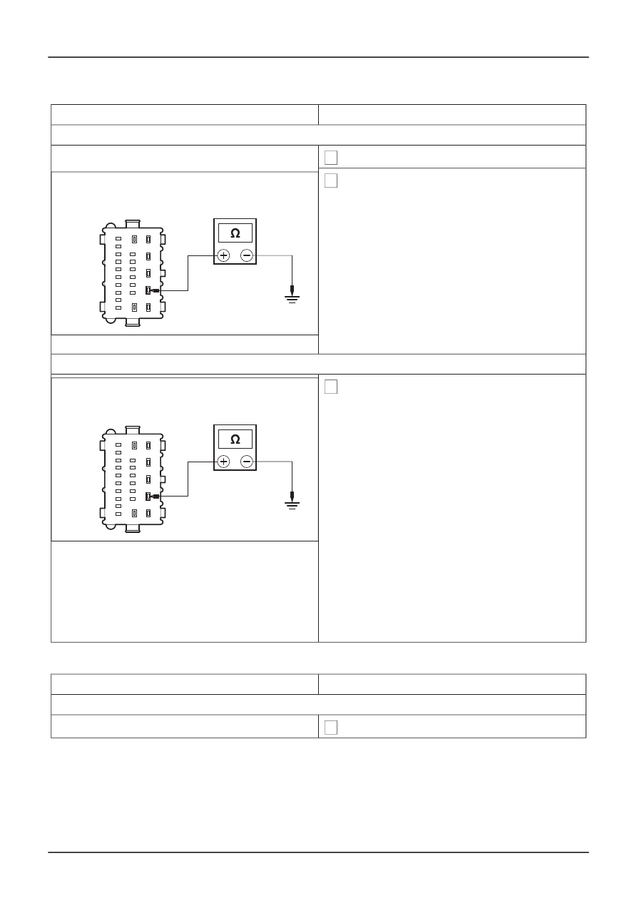
N1: CHECK CIRCUIT 1/2-AB34 (WH/RD) FOR SHORT TO GROUND

1 Disconnect Keyless Vehicle Module C219.

2 Measure the resistance between the keyless

vehicle module C219 pin 2, circuit 1-AB34
(WH/RD), harness side and ground.

• Is the resistance less than 5 ohms?

Yes

E57502

REPAIR circuit 1-AB34 (WH/RD) or 2-AB34
(GY/RD). TEST the system for normal opera-
tion.

No

N2: CHECK CIRCUIT 2-AB34 (GY/RD) FOR SHORT TO BATTERY POSITIVE

1 Measure the resistance between the keyless

vehicle module C219 pin 2, circuit 1-AB34
(WH/RD), harness side and battery positive.

• Is the resistance less than 5 ohms?

Yes

E57502

REPAIR circuit 1-AB34 (WH/RD) or 2-AB34
(GY/RD). TEST the system for normal opera-
tion.

No

Using WDS, CLEAR the DTC. TEST the
system for normal operation. If the DTC is still
present, INSTALL a new keyless vehicle
module.

Handles, Locks, Latches and Entry Systems,
Removal and Installation).

TEST the system for normal operation.

PINPOINT TEST O : DTC: B1077

DETAILS/RESULTS/ACTIONS

TEST CONDITIONS

O1: CHECK CIRCUIT 1/2-AB16 (WH/RD) FOR SHORT TO GROUND

1 Disconnect Keyless Vehicle Module C218.

G167639en

501-14-

55

Handles, Locks, Latches and Entry Systems

501-14-

55

DIAGNOSIS AND TESTING

REFER to: Keyless Vehicle Module

(501-14

GO to N2

.

DETAILS/RESULTS/ACTIONS

TEST CONDITIONS

2 Measure the resistance between the keyless

vehicle module C218 pin 20, circuit 1-AB16
(WH/RD), harness side and ground.

• Is the resistance less than 5 ohms?

Yes

E57507

REPAIR circuit 1-AB16 (WH/RD) or 2-AB16
(GY/RD). TEST the system for normal opera-
tion.

No

O2: CHECK CIRCUIT 1/2-AB16 (WH/RD) FOR SHORT TO BATTERY POSITIVE

1 Measure the resistance between the keyless

vehicle module C218 pin 20, circuit 1-AB16
(WH/RD), harness side and battery positive.

• Is the resistance less than 5 ohms?

Yes

E57507

REPAIR circuit 1-AB16 (WH/RD) or 2-AB16
(GY/RD). TEST the system for normal opera-
tion.

No

Using WDS, CLEAR the DTC. TEST the
system for normal operation. If the DTC is still
present, INSTALL a new keyless vehicle
module.

Handles, Locks, Latches and Entry Systems,
Removal and Installation).

TEST the system for normal operation.

PINPOINT TEST P : DTC: B1083

DETAILS/RESULTS/ACTIONS

TEST CONDITIONS

P1: CHECK CIRCUIT 1-AB27 (WH/RD) FOR SHORT CIRCUIT TO GROUND

1 Disconnect Keyless Vehicle Module C218.

G167639en

501-14-

56

Handles, Locks, Latches and Entry Systems

501-14-

56

DIAGNOSIS AND TESTING

REFER to: Keyless Vehicle Module

(501-14

GO to O2

.

DETAILS/RESULTS/ACTIONS

TEST CONDITIONS

2 Measure the resistance between the keyless

vehicle module C218 pin 22, circuit 1-AB27
(WH/RD), harness side and ground.

• Is the resistance less than 5 ohms?

Yes

E57603

REPAIR circuit 1-AB27 (WH/RD) or 2-AB27
(GY/RD). TEST the system for normal opera-
tion.

No

P2: CHECK CIRCUIT 2-AB27 (GY/RD) FOR SHORT CIRCUIT TO GROUND

1 Disconnect Passenger Side Exterior Front Door

Handle C203.

2 Measure the resistance between the keyless

vehicle module C218 pin 22, circuit 1-AB27
(WH/RD), harness side and battery positive.

• Is the resistance greater than 10,000 ohms?

Yes

E57603

REPAIR circuit 1-AB27 (WH/RD) or 2-AB27
(GY/RD). TEST the system for normal opera-
tion.

No

Using WDS, CLEAR the DTC. TEST the
system for normal operation. If the DTC is still
present, INSTALL a new keyless vehicle
module.

Handles, Locks, Latches and Entry Systems,
Removal and Installation).

PINPOINT TEST Q : DTC: B1086

DETAILS/RESULTS/ACTIONS

TEST CONDITIONS

Q1: CHECK CIRCUIT 1/2-AB10 (WH) FOR SHORT TO GROUND

1 Disconnect Keyless Vehicle Module C219.

G167639en

501-14-

57

Handles, Locks, Latches and Entry Systems

501-14-

57

DIAGNOSIS AND TESTING

REFER to: Keyless Vehicle Module

(501-14

TEST the system for normal operation.

GO to P2

.

DETAILS/RESULTS/ACTIONS

TEST CONDITIONS

2 Measure the resistance between the keyless

vehicle module C219 pin 14, circuit 1-AB10
(WH), harness side and ground.

• Is the resistance less than 5 ohms?

Yes

E57508

REPAIR circuit 1-AB10 WH) or 2-AB10 (GY).
TEST the system for normal operation.

No

Q2: CHECK CIRCUIT 1/2-AB16 (GY/RD) FOR SHORT TO BATTERY POSITIVE

1 Measure the resistance between the keyless

vehicle module C219 pin 14, circuit 1-AB10
(WH), harness side and battery positive.

• Is the resistance less than 5 ohms?

Yes

E57508

REPAIR circuit 1-AB10 (WH) or 2-AB10 (GY).
TEST the system for normal operation.

No

Using WDS, CLEAR the DTC. TEST the
system for normal operation. If the DTC is still
present, INSTALL a new keyless vehicle
module.

Handles, Locks, Latches and Entry Systems,
Removal and Installation).

TEST the system for normal operation.

PINPOINT TEST R : DTC: B1070

DETAILS/RESULTS/ACTIONS

TEST CONDITIONS

R1: CHECK CIRCUIT 1/2-AB35 (WH/BU) FOR SHORT TO GROUND

1 Disconnect Keyless Vehicle Module C219.

2 Measure the resistance between the keyless

vehicle module C219 pin 18, circuit 1-AB35
(WH/BU), harness side and ground.

• Is the resistance less than 5 ohms?

Yes

E74073

REPAIR circuit 1-AB35 (WH/BU) or 2-AB35
(GY/VT). TEST the system for normal opera-
tion.

No

G167639en

501-14-

58

Handles, Locks, Latches and Entry Systems

501-14-

58

DIAGNOSIS AND TESTING

GO to R2.

REFER to: Keyless Vehicle Module

(501-14

GO to Q2

.

DETAILS/RESULTS/ACTIONS

TEST CONDITIONS

R2: CHECK CIRCUIT 1/2-AB35 (GY/RD) FOR SHORT TO BATTERY POSITIVE

1 Measure the resistance between the keyless

vehicle module C219 pin 18, circuit 1-AB35
(WH/BU), harness side and battery positive.

• Is the resistance less than 5 ohms?

Yes

E74073

REPAIR circuit 1-AB35 (WH/BU) or 2-AB35
(GY/VT). TEST the system for normal opera-
tion.

No

R3: CHECK CIRCUIT 1/2-AB35 (WH/BU) FOR SHORT TO GROUND

1 Measure the resistance between the keyless

vehicle module C219 pin 2, circuit 1-AB35A
(WH/BU), harness side and ground.

• Is the resistance less than 5 ohms?

Yes

E57502

REPAIR circuit 1-AB35A (WH/BU) or 2-AB35A
(GY/VT). TEST the system for normal opera-
tion.

No

R4: CHECK CIRCUIT 1/2-AB35 (GY/RD) FOR SHORT TO BATTERY POSITIVE

1 Measure the resistance between the keyless

vehicle module C219 pin 2, circuit 1-AB35A
(WH/BU), harness side and battery positive.

• Is the resistance less than 5 ohms?

Yes

E57502

REPAIR circuit 1-AB35A (WH/BU) or 2-AB35A
(GY/VT). TEST the system for normal opera-
tion.

No

G167639en

501-14-

59

Handles, Locks, Latches and Entry Systems

501-14-

59

DIAGNOSIS AND TESTING

GO to R5

.

GO to R4

.

GO to R3

.

DETAILS/RESULTS/ACTIONS

TEST CONDITIONS

R5: CHECK CIRCUIT 1/2-AB36B (GY/OG) FOR SHORT TO GROUND

1 Measure the resistance between the keyless

vehicle module C219 pin 22, circuit 1-AB36A
(GY/OG), harness side and ground.

• Is the resistance less than 5 ohms?

Yes

E57603

REPAIR circuit 1-AB36A (GY/OG) or 2-AB36A
(WH/GN). TEST the system for normal opera-
tion.

No

R6: CHECK CIRCUIT 1/2-AB35 (GY/RD) FOR SHORT TO BATTERY POSITIVE

1 Measure the resistance between the keyless

vehicle module C219 pin 22, circuit 1-AB36A
(WH/GN), harness side and battery positive.

• Is the resistance less than 5 ohms?

Yes

E57603

REPAIR circuit 1-AB36A (GY/OG) or 2-AB36A
(WH/GN). TEST the system for normal opera-
tion.

No

Using WDS, CLEAR the DTC. TEST the
system for normal operation. If the DTC is still
present, INSTALL a new keyless vehicle
module.

Handles, Locks, Latches and Entry Systems,
Removal and Installation).

TEST the system for normal operation.

PINPOINT TEST S : DTC: B1070

DETAILS/RESULTS/ACTIONS

TEST CONDITIONS

S1: CHECK CIRCUIT 1-AB36B (WH/GN) FOR SHORT CIRCUIT TO GROUND

1 Disconnect Keyless Vehicle Module C219.

G167639en

501-14-

60

Handles, Locks, Latches and Entry Systems

501-14-

60

DIAGNOSIS AND TESTING

REFER to: Keyless Vehicle Module

(501-14

GO to R6

.

DETAILS/RESULTS/ACTIONS

TEST CONDITIONS

2 Measure the resistance between the keyless

vehicle module C219 pin 22, circuit 1-AB36B
(WH/GN), harness side and ground.

• Is the resistance greater than 10,000 ohms?

Yes

E57603

Using WDS, CLEAR the DTC. TEST the
system for normal operation. If the DTC is still
present, INSTALL a new keyless vehicle
module.

Handles, Locks, Latches and Entry Systems,
Removal and Installation).

TEST the system for normal operation.

No

GO to S2.

S2: CHECK CIRCUIT 2-AB36B (GY/OG) FOR SHORT CIRCUIT TO GROUND

1 Disconnect Passenger Compartment Center

Keyless Vehicle Antenna C226.

2 Measure the resistance between the keyless

vehicle module C219 pin 4, circuit 2-AB36B
(GY/OG), harness side and ground.

• Is the resistance greater than 10,000 ohms?

Yes

E57602

GO to S3.

No

REPAIR circuit 2-AB36B (GY/OG). TEST the
system for normal operation.

S3: CHECK CIRCUIT 1-AB36B (WH/GN) FOR SHORT CIRCUIT TO GROUND

1 Measure the resistance between the keyless

vehicle module C219 pin 22, circuit 1-AB36B
(WH/GN), harness side and ground.

• Is the resistance greater than 10,000 ohms?

Yes

E57603

INSTALL a new passenger compartment
center keyless vehicle antenna. TEST the
system for normal operation.

No

REPAIR circuit 1-AB36B (WH/GN). TEST the
system for normal operation.

G167639en

501-14-

61

Handles, Locks, Latches and Entry Systems

501-14-

61

DIAGNOSIS AND TESTING

REFER to: Keyless Vehicle Module

(501-14

PINPOINT TEST T : DTC: B1071

DETAILS/RESULTS/ACTIONS

TEST CONDITIONS

T1: CHECK CIRCUIT 1-AB34 (WH/RD) FOR SHORT CIRCUIT TO GROUND

1 Disconnect Keyless Vehicle Module C219.

2 Measure the resistance between the keyless

vehicle module C219 pin 2, circuit 1-AB34
(WH/RD), harness side and ground.

• Is the resistance less than 5 ohms?

Yes

E57502

REPAIR circuit 1-AB34 (WH/RD) or 2-AB34
(GY/RD). TEST the system for normal opera-
tion.

No

GO to T2.

T2: CHECK CIRCUIT 1/2-AB34 (WH/RD) FOR SHORT TO BATTERY POSITIVE

1 Measure the resistance between the keyless

vehicle module C219 pin 2, circuit 1-AB34
(WH/RD), harness side and battery positive.

• Is the resistance less than 5 ohms?

Yes

E57502

REPAIR circuit 1-AB34 (WH/RD) or 2-AB34
(GY/RD). TEST the system for normal opera-
tion.

No

Using WDS, CLEAR the DTC. TEST the
system for normal operation. If the DTC is still
present, INSTALL a new keyless vehicle
module.

Handles, Locks, Latches and Entry Systems,
Removal and Installation).

TEST the system for normal operation.

PINPOINT TEST U : DTC: B1072

DETAILS/RESULTS/ACTIONS

TEST CONDITIONS

U1: CHECK CIRCUIT 1-AB16 FOR OPEN CIRCUIT

1 Disconnect Keyless Vehicle Module C218.

2 Disconnect Driver Side Exterior Front Door

Handle Keyless Vehicle Antenna C211.

G167639en

501-14-

62

Handles, Locks, Latches and Entry Systems

501-14-

62

DIAGNOSIS AND TESTING

REFER to: Keyless Vehicle Module

(501-14


Content   ..  45  46  47  48   ..