Tesla Model S (2022 year). Manual in english - page 7

Wheels and Tires
Vehicle normal load on the
Load on an individual tire that is determined by distributing to each axle its share of
tire
the curb weight, accessory weight, and normal occupant weight and dividing by two.
Pneumatic Radial Tire Definitions
Bead separation
A breakdown of the bond between components in the bead.
Bias ply tire
A pneumatic tire in which the ply cords that extend to the beads are laid at alternate angles
substantially less than 90 degrees to the center line of the tread.
Carcass
The tire structure, except tread and sidewall rubber which, that when inflated, bears the load.
Chunking
The breaking away of pieces of the tread or sidewall.
Cord
The strands forming the plies in the tire.
Cord separation
The parting of cords from adjacent rubber compounds.
Cracking
Any parting within the tread, sidewall, or inner liner of the tire extending to cord material.
Extra load tire
A tire designed to operate at higher loads and higher inflation pressure than the
corresponding standard tire.
Groove
The space between two adjacent tread ribs.
Inner liner
The layer(s) forming the inside surface of a tubeless tire that contains the inflating medium
within the tire.
Inner liner
The parting of the inner liner from cord material in the carcass.
separation
Load rating
The maximum load that a tire is rated to carry for a given inflation pressure.
Maximum load
The load rating for a tire at the maximum permissible inflation pressure for that tire.
rating
Measuring rim
The rim on which a tire is fitted for physical dimension requirements.
Open splice
Any parting at any junction of tread, sidewall, or inner liner that extends to the cord material.
Outer diameter
The overall diameter of an inflated new tire.
Overall width
The linear distance between the exteriors of the sidewalls of an inflated tire, including
elevations due to labeling, decorations, or protective bands or ribs.
Ply
A layer of rubber-coated parallel cords.
Ply separation
A parting of rubber compound between adjacent plies.
Pneumatic tire
A mechanical device made of rubber, chemicals, fabric and steel or other materials, that,
when mounted on an automotive wheel, provides the traction and contains the gas or fluid
that sustains the load.
Radial ply tire
A pneumatic tire in which the ply cords that extend to the beads are laid at substantially 90
degrees to the center line of the tread.
Reinforced tire
A tire designed to operate at higher loads and at higher inflation pressures than the
corresponding standard tire.
Section width
The linear distance between the exteriors of the sidewalls of an inflated tire, excluding
elevations due to labeling, decoration, or protective bands.
Sidewall
The portion of a tire between the tread and bead.
Sidewall separation
The parting of the rubber compound from the cord material in the sidewall.
Specifications
199
Wheels and Tires
Snow tire
A tire that attains a traction index equal to or greater than 110, compared to the ASTM
E1136-93 (re-approved 2003, incorporated by reference, see §571.5) Standard Reference Test
Tire when using the snow traction test as described in ASTM F1805-00 (incorporated by
reference, see §571.5), and that is marked with an Alpine Symbol specified in S5.5(i) on at
least one sidewall.
Test rim
The rim on which a tire is fitted for testing, and may be any rim listed as appropriate for use
with that tire.
Tread
The portion of a tire that comes into contact with the road.
Tread rib
A tread section running around the circumference of a tire.
Tread separation
The pulling away of the tread from the tire carcass.
Tread wear
The projections within the principal grooves designed to give a visual indication of the
indicators (TWI)
degrees of wear of the tread.
Wheel-holding
The fixture used to hold the wheel and tire assembly securely during testing.
fixture
200
Contacting Tesla Roadside Assistance
Tesla Roadside Assistance is available to you 24 hours a day, 365 days a year, for the duration of your warranty
period. Tesla Roadside Assistance is also available to speak with roadside service professionals to answer any
questions and explain the proper procedure for transporting your vehicle.
When contacting Tesla Roadside Assistance, please provide:
• The Vehicle Identification Number (VIN). The VIN is displayed when you touch Controls > Software. The VIN can
also been seen on the upper dashboard by looking through the driver's side of the windshield.
• Your exact location.
• The nature of the problem.
If available in your region, you can also expedite your request, by choosing the Roadside Assistance option in the
Tesla mobile app.
NOTE: For a detailed description of Tesla's Roadside Assistance policy, go to the support page on the Tesla web site
for your region.
Regional Phone Number(s)
Mexico: 1-800-228-8145
United States and Canada: 1-877-79TESLA (1-877-798-3752)
NOTE: The phone number is also available by touching Controls > Service.
Roadside Assistance
201
Instructions for Transporters
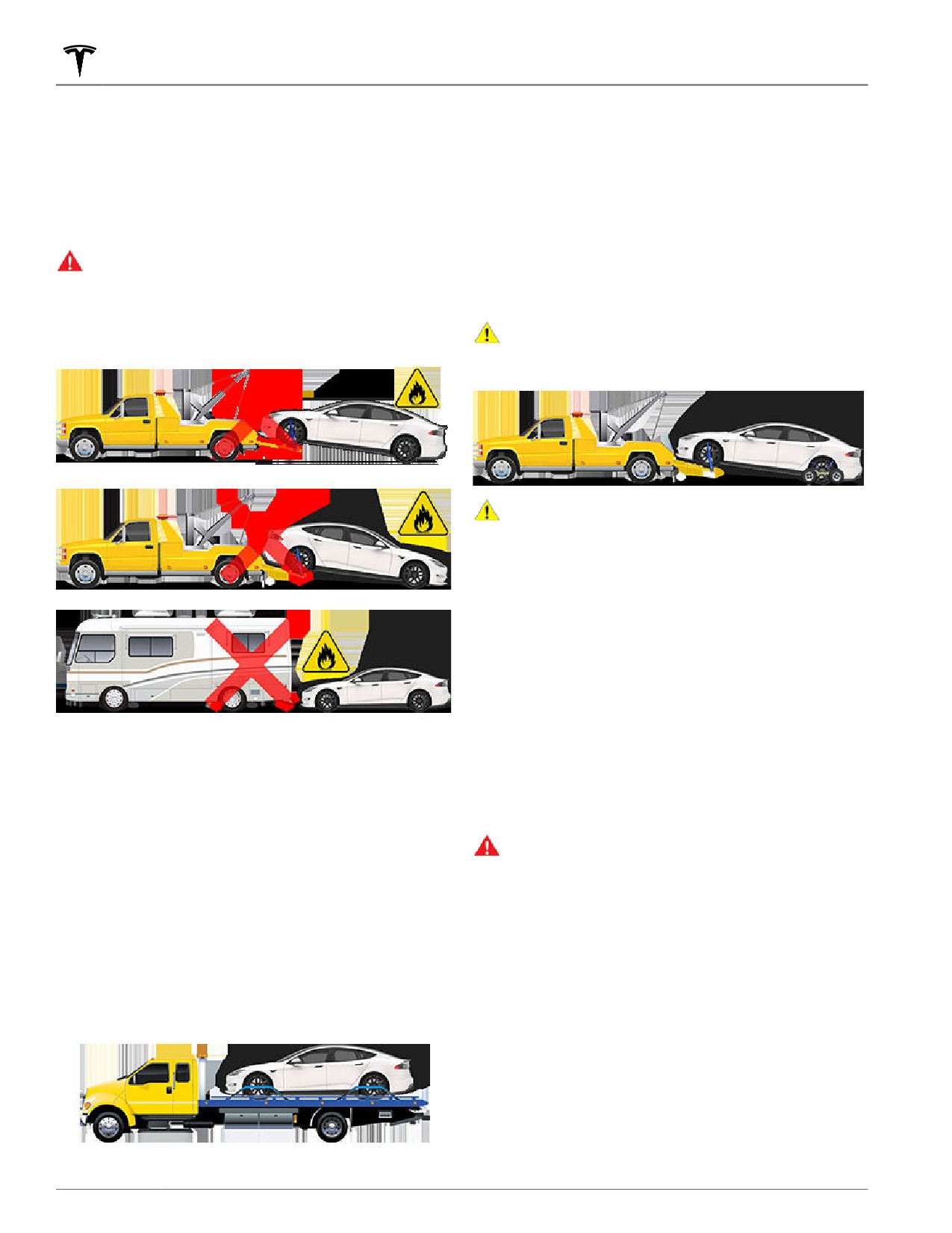
If Model S must be transported without a flatbed truck,
DO NOT TRANSPORT WITH
then wheel lifts and dollies must be used to ensure that
WHEELS ON THE GROUND
all four wheels are off of the ground. This method may
only be used for a maximum of 35 miles (55 km), and
The front and rear motors in Model S generate power
must not exceed the manufacturer speed rating of the
when the wheels spin. Always transport Model S with all
dollies. With this method, Tesla recommends the vehicle
four tires off the ground. Ensure that the tires are unable
faces forward so that the front wheels are lifted and the
to spin at any time during transport.
rear wheels are on dollies.
WARNING: NEVER TRANSPORT YOUR VEHICLE
NOTE: Transporting Model S with the front wheels on
WITH THE TIRES IN A POSITION WHERE THEY
dollies is not recommended, but may be done if an
CAN SPIN. DOING SO CAN LEAD TO SIGNIFICANT
external steering yoke lock is applied and care is taken
to prevent the front wheels from spinning.
DAMAGE AND OVERHEATING. IN RARE CASES
EXTREME OVERHEATING MAY CAUSE THE
CAUTION: DO NOT TRANSPORT YOUR VEHICLE
SURROUNDING COMPONENTS TO IGNITE.
IF THERE IS ANY CHANCE OF ANY OF THE
WHEELS SPINNING.
CAUTION: Enable Transport Mode (see Activate
Transport Mode on page 203) before winching
Model S onto a flatbed truck. If Transport Mode is
not available or the touchscreen is not accessible,
self-loading dollies or tire skates must be used to
load the vehicle into the approved transportation
position. Tesla is not responsible for any damage
caused by or during the transport of Model S,
including personal property damage or damage
caused by using self-loading dollies or tire skates.
NOTE: Transport Mode is only intended to allow for
winching Model S onto a flatbed truck or repositioning
the vehicle out of a parking space. While in Transport
Mode, the tires are allowed to rotate slowly (under 3
Do not transport Model S using any method that is not
mph or 5 km/h) and for a very short distance (less than
specified by Tesla. Adhere to the instructions provided in
30 feet or 10 meters). See Activate Transport Mode on
the following sections and observe all warnings and
page 203. Exceeding these boundaries can lead to
cautions provided. Damage caused by improper
significant damage and overheating that is not covered
transporting of your vehicle is not covered by the
by the warranty.
warranty.
WARNING: Model S is equipped with high voltage
components that may be compromised as a result
NOTE: Tesla is not liable or responsible for reimbursing
of a collision (see High Voltage Components on
services not dispatched through Tesla Roadside
page 162). Before transporting Model S, it is
Assistance.
important to assume these components are
energized. Always follow high voltage safety
Approved Methods for Transporting
precautions (wearing personal protection
equipment, etc.) until emergency response
A flatbed truck or comparable transport vehicle is the
professionals have evaluated the vehicle and can
recommended method of transporting Model S. The
accurately confirm that all high voltage systems
vehicle can face either direction when using a flatbed.
are no longer energized. Failure to do so may
result in serious injury.
Disable the Self-Leveling Air
Suspension System
NOTE: If Model S has no low voltage power, you need an
external low voltage power supply to use the
touchscreen. See If Vehicle Has No Power on page 205.
202
Instructions for Transporters
Your Model S is equipped with an air suspension system
CAUTION: To avoid damage, only pull the vehicle
that automatically self-levels the vehicle, even when
onto a flatbed truck using a properly-installed tow
power is off. To prevent damage, you must activate Jack
eye. Using the chassis, frame, or suspension
mode to disable self-leveling:
components to pull the vehicle can result in
damage.
1. Touch Controls > Suspension on the touchscreen.
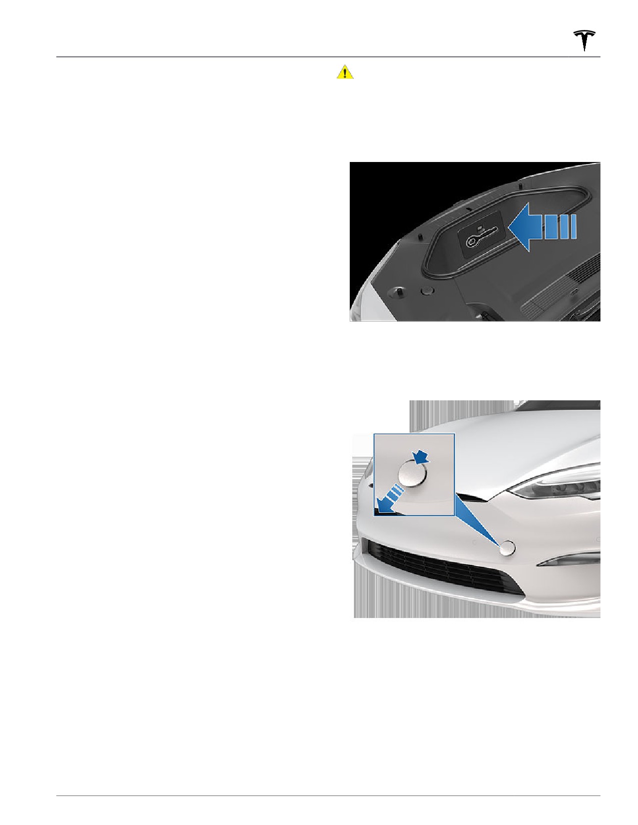
1. Locate the tow eye. The tow eye is located in the
2. Press the brake pedal, and then touch Very High to
front trunk.
maximize height.
3. Touch Controls > Service > Jack Mode.
NOTE: Jack mode cancels when driving speed exceeds
4 mph (7 km/h).
Activate Transport Mode
Transport Mode keeps the parking brake disengaged
while winching Model S onto a flatbed truck. When
active, Transport Mode displays a message indicating
that the vehicle will remain free-rolling. The following are
required to enable Transport Mode:
• Low voltage power. You are unable to use the
touchscreen to activate Transport Mode if Model S
2. Release the front tow eye cover by pressing firmly on
has no power.
its top right perimeter until it pivots inward, then
gently pulling the raised section toward you.
• Model S must detect a key. Transport Mode is
available only when a key is detected.
NOTE: The front tow eye cover is connected to the
vehicle's black negative (-) terminal.
To activate Transport Mode:
1. Ensure the vehicle is in Park.
2. Chock the tires and make sure Model S is secure.
3. Press and hold the brake pedal, and then on the
touchscreen, touch Controls > Service > Towing. The
touchscreen displays a message reminding you how
to properly transport Model S.
4. Press and hold the Transport Mode button until it
turns blue. Model S is now free-rolling and can slowly
be rolled (no faster than walking speed) for short
distances or winched.
To cancel Transport Mode, shift Model S into Park.
NOTE: If the electrical system is not working, and you
therefore cannot use the touchscreen to activate
Transport Mode, use self-loading dollies or tire skates.
Before doing so, always check the manufacturer's
specifications and recommended loading capacity.
3. Fully insert the tow eye into the opening, then turn it
counter-clockwise until securely fastened.
Pull Onto Flatbed Truck From Front
(Using Tow Eye)
NOTE: If Model S has no low voltage power, you need an
external low voltage power supply to open the hood or
use the touchscreen. See If Vehicle Has No Power on
page 205.
Roadside Assistance
203
Instructions for Transporters
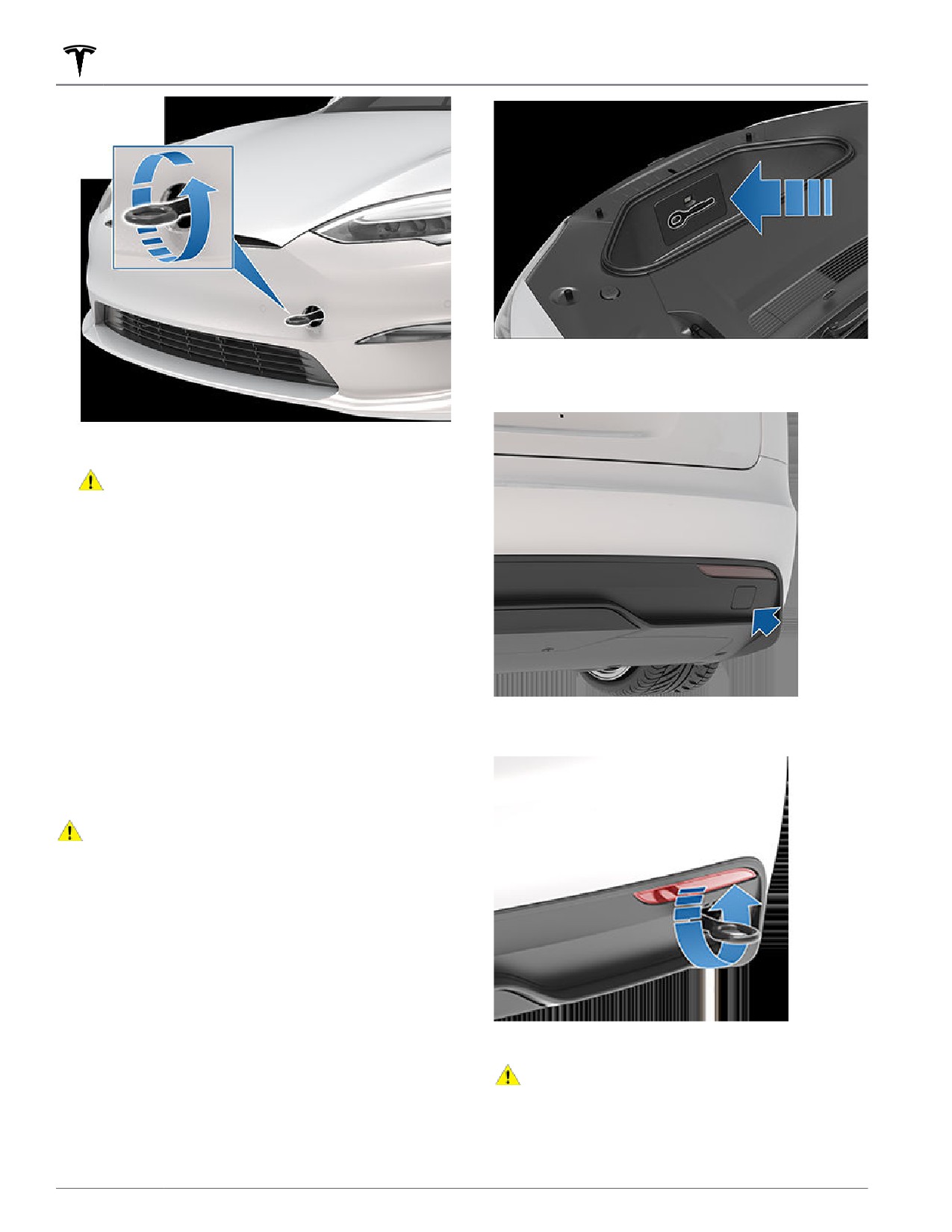
2. Release the rear tow eye cover by pressing firmly on
its bottom perimeter until it pivots inward, then
gently pulling the raised section toward you.
4. Attach the winch cable to the tow eye.
CAUTION: Before pulling, make sure the tow
eye is securely tightened.
5. Activate Transport Mode.
6. Pull Model S slowly onto the flatbed truck.
Pull Onto Flatbed Truck From Rear
(Using Tow Eye)
NOTE: If Model S has no low voltage power, you need an
external low voltage power supply to open the hood or
use the touchscreen. See If Vehicle Has No Power on
page 205.
3. Fully insert the tow eye into the opening, then turn it
NOTE: Vehicles equipped with a hitch receiver cannot be
counter-clockwise until securely fastened.
pulled from the rear tow eye. Use the tow bar or hitch
receiver only to pull the vehicle to a safe location, such
as onto a flatbed truck. Do not transport the vehicle with
wheels on the ground.
CAUTION: To avoid damage, only pull the vehicle
onto a flatbed truck using a properly-installed tow
eye. Using the chassis, frame, or suspension
components to pull the vehicle can result in
damage.
1. Locate the tow eye. The tow eye is located in the
front trunk.
4. Attach the winch cable to the tow eye.
CAUTION: Before pulling, make sure the tow
eye is securely tightened.
5. Activate Transport Mode.
6. Pull Model S slowly onto the flatbed truck.
204
Instructions for Transporters
Pull onto the Flatbed Truck From
Front (Without Tow Eye)
CAUTION: To avoid damage, only pull the vehicle
onto a flatbed truck using a properly-installed tow
eye. Using the chassis, frame, or suspension
components to pull the vehicle can result in
damage.
WARNING: If the vehicle is pulled onto the flatbed
truck using this method, all suspension fasteners
should be checked for proper torque and all
components should be visually inspected for
damage prior to driving the vehicle again. If a
fastener is loose, or if any damage is found, the
affected component(s) should be replaced.
It is strongly recommended that you connect the winch
to your vehicle's tow eye, as described previously.
If Vehicle Has No Power
However, if a situation arises in which the tow eye is not
available (lost, misplaced, etc.), the following
instructions describe how to attach tow straps.
If Model S has no low voltage power, perform the
following steps to open the hood or jump start the
1. Attach the tow straps to each of the lower
auxiliary low voltage battery.
suspension arms underneath the front of the vehicle.
Jump Starting the Low Voltage Battery
CAUTION: Model S cannot be used to jump start
another vehicle. Doing so can result in damage.
NOTE: If jump starting Model S using another vehicle,
refer to that vehicle manufacturer's instructions. The
following instructions assume an external low voltage
power supply (such as a portable jump starter) is used.
CAUTION: Avoid short circuits when jump starting
Model S. Connecting cables to the wrong jump
post, touching leads together, etc., can result in
damage to Model S.
1. Open the hood.
2. To protect the underbody from damage, place a
2. Remove the maintenance panel by pulling it upwards
protective barrier (such as a piece of wood) between
to release the trim clips that hold it in place.
the tow strap and underbody.
3. Activate Transport Mode.
4. Pull Model S slowly onto the flatbed truck.
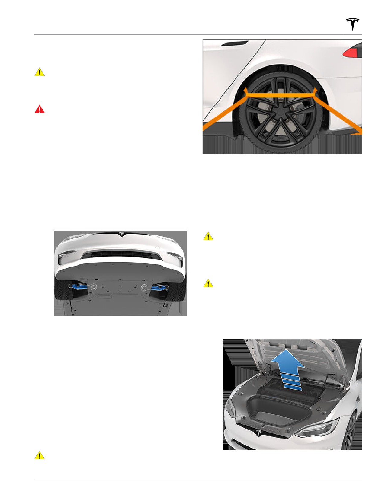
Secure the Tires
The vehicle's tires must be secured onto the truck using
the eight-point tie-down method.
• Ensure any metal parts on the tie-down straps do not
contact painted surfaces or the face of the wheels.
• Do not place tie-down straps over body panels or
through the wheels.
CAUTION: Attaching the tie-down straps to the
chassis, suspension or other parts of the vehicle's
body may cause damage.
Roadside Assistance
205
Instructions for Transporters
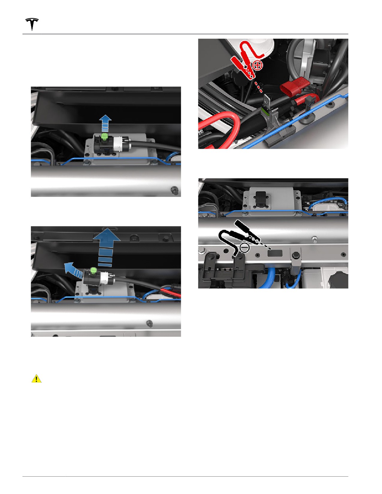
3. On top of the low voltage battery, lift the locking tab
that attaches the electrical connector to the
connector housing.
NOTE: The appearance of the electrical connector
and connector housing may vary, but the procedure
remains the same.
6. Connect the low voltage power supply's black
negative (-) cable to the vehicle in the location
shown.
4. On top of the low voltage battery, pull the connector
housing to the left. The electrical connector releases
from the low voltage battery.
7. Turn on the external power supply (refer to the
manufacturer’s instructions). Touch the touchscreen
to wake it up.
NOTE: It may take several minutes to receive enough
power to wake up the touchscreen.
8. When external low voltage power is no longer
5. Release the cover from the red positive (+) jump
required, disconnect both cables, beginning with the
post, and then connect the low voltage power
black negative (-) cable.
supply's red positive (+) cable to the red positive (+)
9. On top of the low voltage battery, push the
jump post.
connector housing towards the electrical connector
CAUTION: To avoid damaging Model S, do not
so that the electrical connector engages the low
allow the positive cable to contact other metal
voltage battery.
components.
10. On top of the low voltage battery, push down the
locking tab that attaches the electrical connector to
the connector housing.
11. Replace the maintenance panel by placing it back in
its original location and pressing down until it is
secure.
12. Close the hood.
206
About this Owner Information
Document Applicability
For the latest and greatest information that is
your vehicle’s touchscreen by touching Controls >
your vehicle depending on the features you purchased,
vehicle configuration, market region and software
version. In contrast, owner information that is provided
by Tesla elsewhere is updated as necessary and may not
contain information unique to your vehicle.
Information about new features is displayed on the
touchscreen after a software update, and can be viewed
at any time by touching Controls > Software > Release
use your vehicle conflicts with information in the Release
Copyrights and Trademarks
Notes, the Release Notes take precedence.
and all vehicle software is subject to copyright and other
Illustrations
intellectual property rights of Tesla, Inc. and its licensors.
This material may not be modified, reproduced or
The illustrations provided in this document are for
copied, in whole or in part, without the prior written
demonstration purposes only. Depending on vehicle
permission of Tesla, Inc. and its licensors. Additional
options, software version and market region, the
information is available upon request. Tesla uses
information displayed on the touchscreen in your vehicle
software created by the Open Source community. Please
may appear slightly different.
visit Tesla’s Open Source software website at http://
www.tesla.com/opensource. HD Radio is a registered
Feature Availability
trademark of iBiquity Digital Corporation. The following
are trademarks or registered trademarks of Tesla, Inc. in
the United States and other countries:
Some features are available only on some vehicle
configurations and/or only in specific market regions.
does not guarantee they are available on your specific
vehicle.
Errors or Inaccuracies
All specifications and descriptions are known to be
accurate at time of publishing. However, because
continuous improvement is a goal at Tesla, we reserve
the right to make product modifications at any time. To
communicate any inaccuracies or omissions, or to
provide general feedback or suggestions regarding the
ownersmanualfeedback@tesla.com.
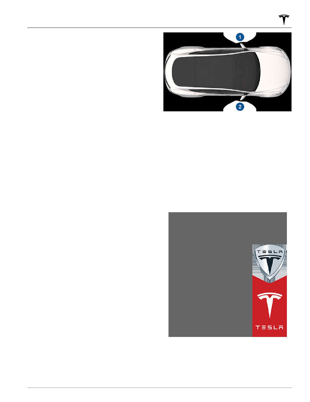
Location of Components
Owner information may specify the location of a
component as being on the left or right side of the
vehicle. As shown, left (1) and right (2) represent the
side of the vehicle when sitting inside.
All other trademarks contained in this document are the
property of their respective owners and their use herein
does not imply sponsorship or endorsement of their
products or services. The unauthorized use of any
trademark displayed in this document or on the vehicle
is strictly prohibited.
Consumer Information
207
Disclaimers
and research by Tesla and its partners for the
Event Data Recorder (EDR)
improvement and design of our vehicles and systems; to
defend Tesla; and as otherwise may be required by law.
Model S is equipped with an event data recorder (EDR).
In servicing your vehicle, Tesla can potentially resolve
The main purpose of an EDR is to record, in certain crash
issues remotely simply by reviewing your vehicle’s data
or near crash-like situations, such as an air bag
log.
deployment or hitting a road obstacle, data to better
understand how the vehicle's systems performed. The
Tesla’s telematics system wirelessly transmits vehicle
EDR is designed to record data related to vehicle
information to Tesla on a periodic basis. The data is used
dynamics and safety systems for a short period of time,
as previously described and helps ensure the proper
typically 30 seconds or less. The EDR in Model S is
maintenance of your vehicle. Additional Model S features
designed to record data such as:
may use your vehicle’s telematics system and the
information provided, including features such as
• How various systems in your vehicle were operating;
charging reminders, software updates, and remote
access to, and control of, various systems of your
• Whether or not the driver and passenger safety belts
vehicle.
were buckled/fastened;
• How far (if at all) the driver was depressing the
Tesla does not disclose the data recorded in your vehicle
accelerator and/or brake pedal; and,
to any third party except when:
• How fast the vehicle was traveling.
• An agreement or consent from the vehicle’s owner
(or the leasing company for a leased vehicle) is
The data can help provide a better understanding of the
obtained.
circumstances in which crashes and injuries occur.
• O
cially requested by the police or other authorities.
NOTE: EDR data is recorded by your vehicle only if a
• Used as a defense for Tesla.
non-trivial crash situation occurs; no data is recorded by
the EDR under normal driving conditions and no
• Ordered by a court of law.
personal data (for example, name, gender, age, and
• Used for research purposes without disclosing details
crash location) is recorded. However, other parties, such
of the vehicle owner or identification information.
as law enforcement, could combine the EDR data with
the type of personally identifying data routinely
• Disclosed to a Tesla a
liated company, including
acquired during a crash investigation.
their successors or assigns, or our information
systems and data management providers.
To read data recorded by an EDR, special equipment is
required, and access to the vehicle or the EDR is needed.
For additional information regarding how Tesla
In addition to the vehicle manufacturer, other parties,
processes data collected from your vehicle, please
such as law enforcement, that have the special
review Tesla's Privacy Notice at http://www.tesla.com/
equipment, can read the information if they have access
about/legal.
to the vehicle or the EDR. Tesla may also access the EDR
remotely in some crash circumstances.
Data Sharing
Vehicle Telematics
For quality assurance and to support the continuous
improvement of advanced features such as Autopilot,
Model S is equipped with electronic modules that
your Model S may collect analytics, road segment,
monitor and record data from various vehicle systems,
diagnostic, and vehicle usage data and send to Tesla for
including the motor, Autopilot components, Battery,
analysis. This analysis helps Tesla improve products and
braking and electrical systems. The electronic modules
services by learning from the experience of billions of
record information about various driving and vehicle
miles that Tesla vehicles have driven. Although Tesla
conditions, including braking, acceleration, trip and
shares this data with partners that contribute similar
other related information regarding your vehicle. These
data, the collected information does not identify you
modules also record information about the vehicle’s
personally and can be sent to Tesla only with your
features such as charging events and status, the
explicit consent. In order to protect your privacy,
enabling/disabling of various systems, diagnostic
personal information is either not logged at all, is subject
trouble codes, VIN, speed, direction and location.
to privacy preserving techniques, or is removed from
any reports before being sent to Tesla. You have control
The data is stored by the vehicle and may be accessed,
over what data you share by touching Controls >
used and stored by Tesla service technicians during
Software > Data Sharing.
vehicle servicing or periodically transmitted to Tesla
wirelessly through the vehicle’s telematics system. This
For additional information regarding how Tesla
data may be used by Tesla for various purposes,
processes data collected from your vehicle, please
including, but not limited to: providing you with Tesla
review Tesla's Privacy Notice at http://www.tesla.com/
telematics services; troubleshooting; evaluation of your
about/legal.
vehicle’s quality, functionality and performance; analysis
208

Disclaimers
NOTE: Although Model S uses GPS in connection with
driving and operation, as discussed in this owner's
manual, Tesla does not record or store vehicle-specific
GPS information, except the location where a crash
occurred. Consequently, Tesla is unable to provide
historical information about a vehicle's location (for
example, Tesla is unable to tell you where Model S was
parked/traveling at a particular date/time).
Quality Control
You might notice a few miles/km on the odometer when
you take delivery of your Model S. This is a result of a
comprehensive testing process that ensures the quality
of your Model S.
The testing process includes extensive inspections
during and after production. The final inspection takes
place at Tesla and includes a road test conducted by a
technician.
California Proposition 65
WARNING: Operating, servicing and maintaining a
passenger vehicle or off-highway motor vehicle
can expose you to chemicals including phthalates
and lead, which are known to the State of
California to cause cancer and birth defects or
other reproductive harm. To minimize exposure,
wear gloves or wash your hands frequently when
servicing your vehicle. For more information go to:
www.P65Warnings.ca.gov/passenger-vehicle.
WARNING: Certain components of this vehicle
such as airbag modules and seat belt pre-
tensioners may contain Perchlorate Material.
Special handling may be required for service or
vehicle end of life disposal. See www.dtsc.ca.gov/
hazardouswaste/perchlorate.
WARNING: Battery posts, terminals, and related
accessories contain lead and lead compounds.
Wash hands after handling.
Consumer Information
209
Reporting Safety Defects
Contacting Tesla
For detailed information about your Model S, go to
or sign up to get an account.
If you have any questions or concerns about your
Model S, in the United States, Canada or Puerto Rico,
call 1-877-79TESLA (1-877-798-3752) and in Mexico, call
1-800-228-8145.
NOTE: You can also use voice commands to provide
feedback to Tesla. Say "Report", "Feedback", or "Bug
report" followed by brief comments. Model S takes a
snapshot of its systems, including your current location,
vehicle diagnostic data, and screen captures of the
touchscreen and instrument panel. Tesla periodically
reviews these notes and uses them to continue
improving Model S.
Reporting Safety Defects - US
If you believe that Model S has a defect which could
cause a crash or could cause injury or death, you should
immediately inform the National Highway Tra
c Safety
Administration (NHTSA) in addition to notifying Tesla.
If NHTSA receives similar complaints, it may open an
investigation. If it finds that a safety defect exists in a
group of vehicles, it may order a recall and remedy
campaign. However, NHTSA cannot become involved in
individual problems between you, your dealer, or Tesla.
To contact NHTSA, you may call the Vehicle Safety
Hotline toll-free at 1-888-327-4236
(TTY: 1-800-424-9153); go to www.safercar.gov; or write
to: Administrator, National Highway Tra
c Safety, 1200
New Jersey Avenue SE., Washington, DC 20590. You can
also obtain other information about motor vehicle safety
from www.safercar.gov.
Reporting Safety Defects - Canada
If you believe that your Model S has a defect which
could cause a crash or could cause injury or death, you
should immediately inform Transport Canada, in addition
to notifying Tesla. To contact Transport Canada, call their
toll-free number: 1-800-333-0510.
210
Radio Regulatory Compliance
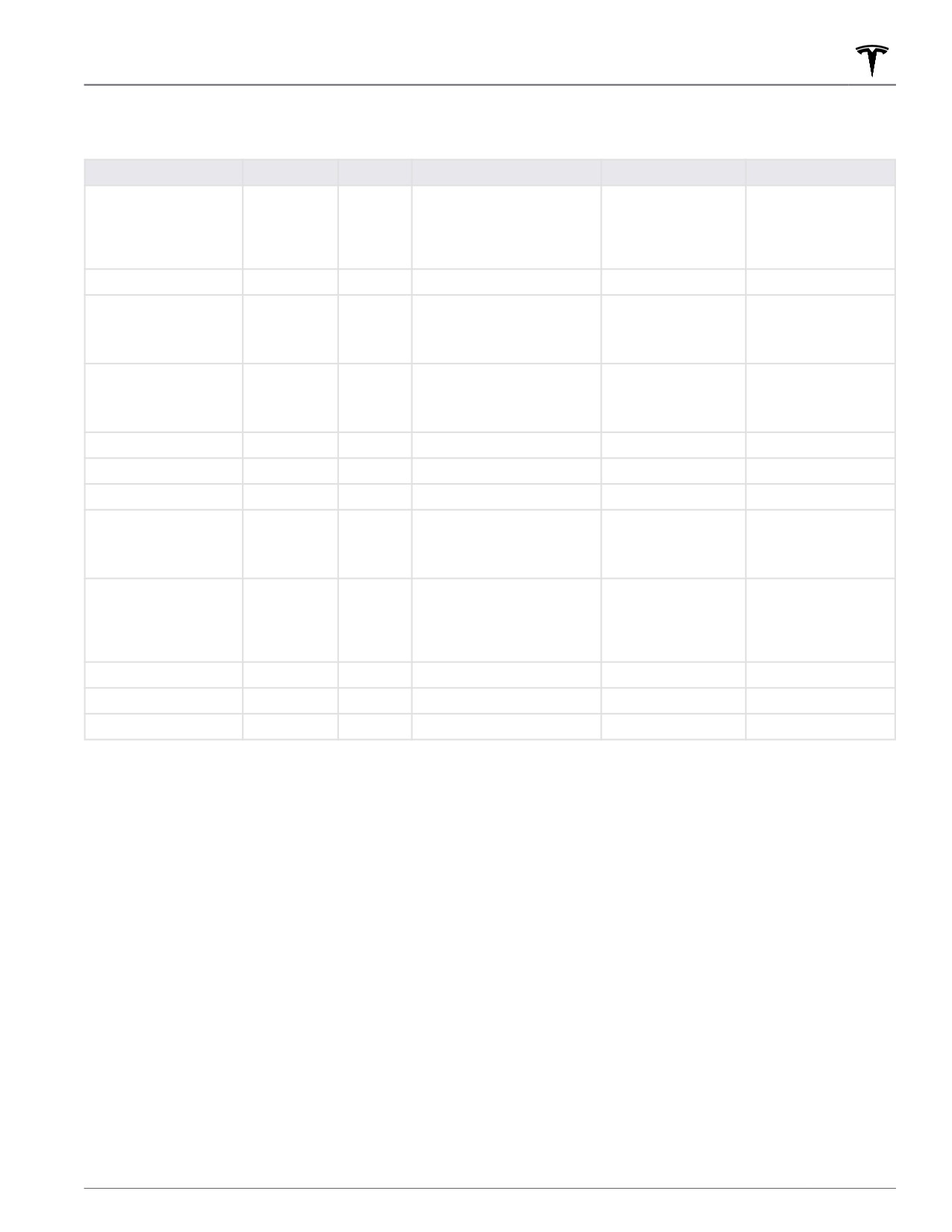
FCC and IC Certification
Component
Manufacturer
Model
Operating Frequency (MHz)
FCC ID
IC
B Pillar Endpoint
Tesla
1614291
2AEIM-1614291
20098-1614291
13.56
2400-2483.5
6000-8500
Security Controller
Tesla
1614280
2400-2483.5
2AEIM-1614280
20098-1614280
Fascia Endpoint
Tesla
1613851
2AEIM-1613851
20098-1613851
2400-2483.5
6000-8500
Key fob
Tesla
1614283
2AEIM-1614283
20098-1614283
2400-2483.5
6000-8500
TPMS
Tesla
1472547G
2400-2483.5
2AEIM-1472547G
20098-1472547G
Radar (if equipped)
Continental
ARS 4-B
76000-77000
OAYARS4B
4135A-ARS4B
Homelink (if equipped)
Gentex
ADHL5C
286-440MHz
NZLADHL5C
4112A-ADHL5C
CarPC
Tesla
1960000
--
XMR2020AG525RGL
10224A-2020AG525R
YZP-ATC5CPC001
7414C-ATC5CPC001
Wireless Charger
Tesla
WC4
2AEIM-WC4
20098-WC4
127.72 KHz
13.56
2400-2483.5
Wireless Charger
Tesla
WC3
127.72KHz
2AEIM-WC3
20098-WC3
BT USB hub
Tesla
1642783
2400-2483.5
2AEIM-1642783
20098-1642783
In-cabin radar*
Tesla
1616631
60000-64000
2AEIM-1616631
20098-1616631
* The in-cabin radar is restricted to factory installation.
The devices listed above comply with Part 15 of the FCC rules and Industry Canada's license-exempt RSS
Standard(s) and EU Directive 2014/53/EU.
Operation is subject to the following two conditions: (1) this device may not cause harmful interference, and (2) this
device must accept any interference received, including interference that may cause undesired operation.
Changes or modifications not expressly approved by Tesla could void your authority to operate the equipment.
Le présent appareil est conforme aux CNR d'Industrie Canada applicables aux appareils radio exempts de licence.
L'exploitation est autorisée aux deux conditions suivantes : (1) l'appareil ne doit pas produire de brouillage, et (2)
l'utilisateur de l'appareil doit accepter tout brouillage radioélectrique subi, même si le brouillage est susceptible d'en
compromettre le fonctionnement.
Radiation Exposure Statement
The products comply with the FCC/IC RF Exposure for Low Power Consumer Wireless Power Transfer. RF exposure
limits are set forth for an uncontrolled environment and are safe for intended operation as described in this manual.
The farthest RF exposure demonstrated by compliance was at 20cm and farther from the user's body; set the device
to low output power if such function is available.
Consumer Information
211
Radio Regulatory Compliance
Cet équipement est conforme aux limites d’exposition aux rayonnements IC établies pour unenvironnement non
contrôlé.
Déclaration d'exposition aux radiations
Le produit est conforme à l'exposition RF IC pour le transfert de puissance sans fil de consommateurs de faible
puissance. La limite d'exposition RF fixée pour un environnement non contrôlé est sans danger pour le
fonctionnement prévu tel que décrit dans ce manuel. L'exposition RF supplémentaire que la conformité a été
démontrée à 20cm et plus de séparation du corps de l'utilisateur ou de mettre l'appareil à la puissance de sortie
inférieure si une telle fonction est disponible.
Mexico
IFT-008-SCFI-2015 / NOM-208-SCFI-2016
Key fob, model: 1614283, IFT#: RLVTE1621-3394
TPMS, model: 1472547G, IFT#: RCPTE1421-4384
La operación de este equipo está sujeta a las siguientes dos condiciones:
1. Es posible que este equipo o dispositivo no cause interferencia perjudicial.
2. Este equipo debe aceptar cualquier interferencia, incluyendo la que pueda causar su operación no deseada.
Radio Frequency Information
This equipment has been tested and found to comply with the limits for a Class B digital device, pursuant to Part 15
of the FCC Rules. These limits are designed to provide reasonable protection against harmful interference in a
residential installation. This equipment generates, uses and can radiate radio frequency energy and, if not installed
and used in accordance with the instructions, may cause harmful interference to radio communications. However,
there is no guarantee that interference will not occur in a particular installation. If this equipment does cause harmful
interference to radio or television reception, which can be determined by turning the equipment off and on, try to
correct the interference by one or more of the following measures:
• Reorient or relocate the receiving antenna.
• Increase the separation between the equipment and receiver.
• Connect the equipment into an outlet on a circuit different from that to which the receiver is connected.
• Consult the dealer or an experienced radio/TV technician to help.
CAUTION: This equipment and its antennas must not be co-located or operated with another antenna or
transmitter.
Canada
CAN ICES-003 (B)/NMB-003(B)
Le présent appareil est conforme aux CNR d'Industrie Canada applicables aux appareils radioexempts de licence.
L'exploitation est autorisée aux deux conditions suivantes : (1) l'appareilne doit pas produire de brouillage, et (2)
l'utilisateur de l'appareil doit accepter tout brouillage radioélectrique subi, même si le brouillage est susceptible d'en
compromettre lefonctionnement.
Cet équipement est conforme aux limites d’exposition aux rayonnements IC établies pour unenvironnement non
contrôlé.
212
Radio Regulatory Compliance
Déclaration d'exposition aux radiations
Le produit est conforme à l'exposition RF IC pour le transfert de puissance sans fil de consommateurs de faible
puissance. La limite d'exposition RF fixée pour un environnement non contrôlé est sans danger pour le
fonctionnement prévu tel que décrit dans ce manuel. L'exposition RF supplémentaire que la conformité a été
démontrée à 20cm et plus de séparation du corps de l'utilisateur ou de mettre l'appareil à la puissance de sortie
inférieure si une telle fonction est disponible.
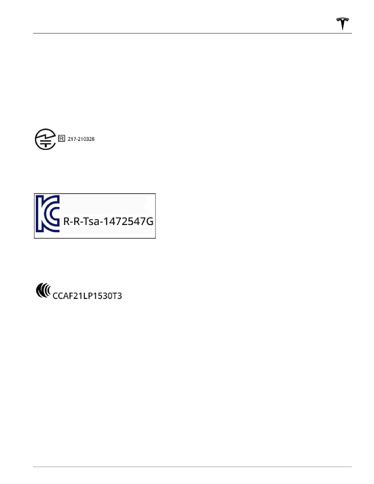
Japan
Korea
TPMS
Taiwan
TPMS:
Consumer Information
213
Troubleshooting Alerts
(APP_w207)
Autosteer temporarily unavailable
Autosteer is currently unavailable. This could be a temporary condition due to external conditions that include:
• Missing or faded lane markers
• Narrow or winding roads
• Poor visibility due to rain, snow, fog, or other weather conditions
• Extremely hot or cold temperatures
• Bright light due to other vehicle headlights, direct sunlight, or other light sources
If the alert is caused by a temporary factor like these, no action or service is typically needed. Continue to your
destination. The alert will clear and Autosteer will be available once the condition is no longer present.
Please note that the minimum speed to initiate Autosteer when there is no vehicle detected ahead of you and while
driving on a road with visible lane markings is 18 mph (30 km/h), unless certain vehicle and environmental conditions
are met. If a vehicle is detected ahead of you:
• You can initiate Autosteer at any speed under 90 mph (150 km/h).
• You can even initiate Autosteer when stationary, provided the other vehicle is at least 5 feet (150 cm) in front of
you.
This alert will be present if you have temporarily exceeded 90 mph (150 km/h) with Autosteer active, and Autosteer
will not be available for the rest of your current drive.
NOTE: If this alert becomes active while you are driving in Germany, Autosteer should again be available once your
vehicle is traveling below 90 mph (150 km/h).
If Autosteer is not available by the time you reach your destination, and remains unavailable during your next
planned drive, the problem might be one of these issues:
• Damage or obstruction caused by mud, ice, snow, or other environmental factors
• Obstruction caused by an object mounted on the vehicle, like a bike rack
• Obstructions caused by adding paint or adhesive products like wraps, stickers, or rubber coatings to your vehicle
• A damaged or misaligned bumper
The solution might be as simple as washing your vehicle. If you do not find any obvious obstructions or you find
damage to the vehicle, schedule service at your convenience. Your vehicle is OK to drive in the meantime.
For more information, see Autosteer on page 88.
(APP_w218)
Autosteer speed limit exceeded
Take control of
steering yoke
Autosteer is unavailable because your vehicle has exceeded the maximum speed limit for this driver assistance
feature. Autosteer is only available at speeds up to 90 mph (150 km/h).
Take immediate control of the steering yoke and maintain control until you reach your destination. Your vehicle is OK
to drive.
In most cases, Autosteer will not be available for the rest of your current drive. To reset it, you will need to bring the
vehicle to a complete stop and shift into Park. When you shift into Drive to travel to your next destination, Autosteer
should again be available.
214
Troubleshooting Alerts
Please note that the minimum speed to initiate Autosteer when there is no vehicle detected ahead of you and while
driving on a road with visible lane markings is 18 mph (30 km/h), unless certain vehicle and environmental conditions
are met.
If a vehicle is detected ahead of you:
• You can initiate Autosteer at any speed under 90 mph (150 km/h).
• You can even initiate Autosteer when stationary, provided the other vehicle is at least 5 feet (150 cm) in front of
you.
NOTE: If this alert becomes active while you are driving in Germany, Autosteer should again be available once your
vehicle is traveling below 90 mph (150 km/h).
If Autosteer is not available during your next drive, and remains unavailable throughout subsequent drives, schedule
service at your convenience. Your vehicle is OK to drive in the meantime.
For more information, see Autosteer on page 88.
(APP_w221)
Cruise control unavailable
Reduced front radar visibility
Tra
c-Aware Cruise Control and Autosteer are unavailable because the radar located in the front bumper area of
your vehicle has no or low visibility. Continue to your destination. Your vehicle is OK to drive.
Tra
c-Aware Cruise Control and Autosteer will remain unavailable as long as the radar lacks adequate visibility. This
could be a temporary obstruction caused by factors like snow, ice, dirt, or mud. If the alert is caused by a temporary
factor like these, no action might be needed: the condition might clear during your drive.
If the alert persists throughout your drive, examine the front bumper before your next planned drive and attempt to
clear any obstruction.
• See the About Autopilot on page 81 sections “How It Works” and “Cleaning Cameras and Sensors” for more on
the radar location and care needed if clearing dirt / debris from that area of the vehicle.
• See Cleaning on page 178 for general cleaning tips and cautions.
Once the radar regains adequate visibility, the alert will clear and both Tra
c-Aware Cruise Control and Autosteer
should again be available.
If this alert persists throughout subsequent drives but no obstruction is visible on the front bumper where the radar
is located, schedule service at your earliest convenience. Your vehicle is OK to drive in the meantime.
(APP_w222)
Cruise control unavailable
Reduced front camera visibility
Tra
c-Aware Cruise Control and Autosteer are unavailable because one or more of the front cameras in your vehicle
is blocked or blinded by external conditions. Continue to your destination. Your vehicle is OK to drive.
Tra
c-Aware Cruise Control and Autosteer will remain unavailable while a front camera lacks adequate visibility.
Cameras can be blocked or blinded due to many factors that include:
• Dirt or debris on the camera surface
• Environmental conditions like rain, fog, snow, or dew
• Bright sunlight or glare from another light source
• Condensation (water droplets or mist) on the camera surface
Consumer Information
215
Troubleshooting Alerts
This is often a temporary issue that will clear up when condensation evaporates or a particular environmental
condition is no longer present.
If the alert does not clear by the end of your drive, inspect and clean the front camera area at the top center of the
windshield before your next planned drive. Check the camera surface for condensation, dirt, or other debris and
attempt to clear any obstruction. See the About Autopilot on page 81 sections “How It Works” and “Cleaning
Cameras and Sensors” for more on front camera location and tips for careful cleaning.
Although condensation on the inside of the front camera enclosure cannot be wiped clean, you can usually clear it
quicker by following these steps:
1. Pre-condition the cabin with the temperature set to High and A/C turned ON.
2. Turn on the front windshield defroster.
Once all front cameras regain adequate visibility, the alert will clear and both Tra
c-Aware Cruise Control and
Autosteer should again be available.
If this alert persists throughout subsequent drives but no front camera obstruction is visible, schedule service at your
earliest convenience. Your vehicle is OK to drive in the meantime.
(APP_w224)
Cruise control unavailable
Continue driving to allow cameras to calibrate
Tra
c-Aware Cruise Control and Autosteer are unavailable because the cameras on your vehicle are not fully
calibrated. Continue to your destination. Your vehicle is OK to drive.
Tra
c-Aware Cruise Control and Autosteer will remain unavailable until camera calibration is complete.
Your vehicle must maneuver with great precision when features like Tra
c-Aware Cruise Control and Autosteer are
active. Before these features can be used for the first time, the cameras must complete an initial self-calibration.
Occasionally, one or more cameras can become uncalibrated.
For your convenience, a calibration progress indicator is displayed on the touchscreen. Calibration typically
completes after your vehicle has driven 20-25 miles (32-40 km), but the distance varies depending on road and
environmental conditions. For example, driving on a straight road with highly visible lane markings helps the
cameras calibrate quicker.
See Drive to Calibrate Cameras on page 82 for more information.
When calibration is complete, Tra
c-Aware Cruise Control and Autosteer should be available.
If the alert persists and camera calibration has not completed after your vehicle has driven 100 miles (160 km) or
more, or Tra
c-Aware Cruise Control and Autosteer remain unavailable despite successful camera calibration,
schedule service at your earliest convenience. Your vehicle is OK to drive in the meantime.
(APP_w304)
Camera blocked or blinded
Clean camera or wait for it to regain visibility
One or more of the vehicle cameras is blocked or blinded due to external conditions. When the cameras cannot
provide accurate visual information, some or all Autopilot features may be temporarily unavailable.
Cameras can be blocked or blinded due to many factors, including:
• Dirt or debris on the camera surface
• Environmental conditions like rain, fog, snow, or dew
• Bright sunlight or glare from another light source
• Condensation (water droplets or mist) on the camera surface
216
Troubleshooting Alerts
Continue to your destination. Your vehicle is OK to drive.
This is often a temporary issue that will be resolved when condensation evaporates or a particular environmental
condition is no longer present.
If the alert does not clear by the time you reach your destination, check camera surfaces for condensation, dirt, or
other debris.
For camera locations, see About Autopilot on page 81.
Clean the cameras as necessary before your next planned drive. For recommended cleaning procedures, see
Cleaning Cameras and Sensors on page 83.
If you continue to see this alert after cleaning the cameras, check the inside surfaces of the door pillar camera
enclosures for condensation.
Although condensation inside the camera enclosures cannot be wiped clean, you can usually clear it faster by
following these steps:
1. Pre-condition the cabin with the temperature set to High and A/C turned ON.
2. Turn on the front windshield defroster.
3. Direct the air vents toward the door pillar cameras.
For more information on clearing condensation from camera enclosures, see Cleaning Cameras and Sensors on page
83.
If the alert does not clear by the end of your next planned drive, despite cleaning the indicated camera(s) and
following recommended steps to clear condensation, schedule service at your next convenient opportunity. Your
vehicle is OK to drive in the meantime.
(BMS_a064)
Maximum battery charge level reduced
OK to drive - Schedule service
Your vehicle has detected a condition internal to the high voltage battery that is limiting the battery’s performance.
As a result, maximum charge level and range are reduced. Service is required to restore full performance.
Your vehicle is OK to drive and charge.
If this alert persists, schedule service soon. Without service, your vehicle's maximum charge level and range will
remain limited.
For more information on the high voltage battery, see High Voltage Battery Information on page 164.
(BMS_a066)
Maximum charge level and range may be reduced
OK to drive - Schedule service soon
Your vehicle has detected a condition internal to the high voltage battery that is limiting the battery’s performance.
As a result, maximum charge level and range may be reduced. Service is required to restore full performance.
Your vehicle is OK to drive.
If this alert persists, schedule service at your earliest convenience. Without service, you may notice further
reductions in your vehicle's maximum charge level and range.
For more information on the high voltage battery, see High Voltage Battery Information on page 164.
Consumer Information
217
Troubleshooting Alerts
(BMS_a067)
High voltage battery performance limited
OK to drive - Schedule service soon
Your vehicle has detected a condition internal to the high voltage battery that is limiting the battery’s performance.
Service is required to restore full performance.
Your vehicle is OK to drive.
You may notice that your vehicle's maximum range is reduced.
You may also notice that your vehicle takes longer to charge than before (maximum charge rate may vary, as always,
based on location, power source, and charging equipment).
While this alert remains present, it is recommended that you keep your vehicle charged to 30% capacity or higher.
This can help avoid any discrepancy between the estimated range displayed on your vehicle's touchscreen and the
actual high voltage battery charge level.
It is recommended that you schedule service at your earliest convenience. Without service, your vehicle may
continue to show further reductions in maximum range and charging performance, and may also begin to show
reduced power and acceleration when driving.
For more information on the high voltage battery, see High Voltage Battery Information on page 164.
(BMS_a068)
High voltage battery requires service
Acceleration and charging performance reduced
Your vehicle has detected a condition internal to the high voltage battery that is limiting the battery’s performance.
Service is required to restore full performance.
Your vehicle is OK to drive.
You may notice that your vehicle's top speed is reduced and it responds slower than previously to acceleration
requests. Your vehicle's maximum range may also be reduced.
You may also notice that your vehicle takes longer to charge than before (maximum charge rate may vary, as always,
based on location, power source, and charging equipment).
While this alert remains present, it is recommended that you keep your vehicle charged to 30% capacity or higher.
This can help avoid any discrepancy between the estimated range displayed on your vehicle's touchscreen and the
actual high voltage battery charge level.
It is recommended that you schedule service at your earliest opportunity. Without service, your vehicle may continue
to show reduced power, acceleration, range, and charging performance.
For more information on the high voltage battery, see High Voltage Battery Information on page 164.
(BMS_a069)
Battery charge level low
Charge now
Your vehicle has detected that the high voltage battery does not have enough energy remaining to support driving.
It is recommended that you charge your vehicle immediately.
Your vehicle will be unable to drive or continue driving until charged.
If this alert is present while you are driving, your vehicle needs to shut down. A separate vehicle alert should be
present to indicate this condition. It is also possible your vehicle may shut down unexpectedly.
218
Troubleshooting Alerts
If this alert is present when your vehicle is parked, you may be unable to drive.
This alert is usually present because your vehicle's high voltage battery charge level has been reduced through
normal operation.
Charging your vehicle should restore your vehicle's ability to drive.
If this alert occurs during subsequent drives, despite a displayed battery charge level of 5% or higher, it is
recommended that you schedule service at your earliest convenience.
For more information on the high voltage battery, see High Voltage Battery Information on page 164.
For more information on charging, see Charging Instructions on page 165.
(CC_a001)
Unable to charge - Insucient grounding
Proper wiring or outlet grounding must be verified
What this alert means:
No ground connection detected in the Wall Connector.
What to do:
Have the Wall Connector inspected by an electrician to make sure it is properly grounded. Your electrician should
ensure there is proper grounding at your circuit breaker or power distribution box and also ensure that appropriate
connections are made to the Wall Connector.
For more information, see the installation guide for your Wall Connector.
(CC_a002)
Unable to charge - Insucient grounding
Disconnect and retry or use different equipment
What this alert means:
Ground fault. Current is leaking through an unsafe path. Possible Line to ground or Neutral to ground fault.
What to do:
Try charging again by disconnecting the Wall Connector from the vehicle and reconnecting. If the issue persists, turn
OFF the circuit breaker servicing the Wall Connector, wait 10 seconds, turn the circuit breaker ON again, then try
reconnecting the Wall Connector to the vehicle. If the issue persists, consult your electrician or contact Tesla.
For more information, see the installation guide for your Wall Connector.
(CC_a003)
Unable to charge - Wall Connector GFCI tripped
Disconnect and retry or use different equipment
What this alert means:
Ground fault. Current is leaking through an unsafe path. Possible Line to ground or Neutral to ground fault.
What to do:
Try charging again by disconnecting the Wall Connector from the vehicle and reconnecting. If the issue persists, turn
OFF the circuit breaker servicing the Wall Connector, wait 10 seconds, turn the circuit breaker ON again, then try
reconnecting the Wall Connector to the vehicle. If the issue persists, consult your electrician or contact Tesla.
Consumer Information
219
Troubleshooting Alerts
For more information, see the installation guide for your Wall Connector.
(CC_a004)
Unable to charge - Wall Connector issue
Wall Connector needs service
What this alert means:
Wall Connector hardware issue. Possible issues include:
1. Contactor not working
2. Self-test of internal ground fault monitoring circuit failed
3. Thermal sensor disconnected
4. Other hardware component issues
What to do:
An internal issue was detected by the Wall Connector.
1. Try charging again by disconnecting the Wall Connector from the vehicle and reconnecting.
2. If the issue persists, turn OFF the circuit breaker for the Wall Connector, wait 10 seconds, and turn the circuit
breaker ON again. Then try reconnecting the Wall Connector to the vehicle.
3. If the issue persists, have an electrician make sure all wires are properly connected and torqued according to the
instructions in the Wall Connector Installation Manual.
4. Once your electrician has completed all work and restored power to the Wall Connector, try charging again by
reconnecting the Wall Connector to the vehicle.
5. If the issue persists, the Wall Connector requires service.
For more information, see the installation guide for your Wall Connector.
(CC_a005)
Unable to charge - Wall Connector GFCI tripped
Disconnect and retry or use different equipment
What this alert means:
Ground fault. Current is leaking through an unsafe path. Possible Line to ground or Neutral to ground fault.
What to do:
Try charging again by disconnecting the Wall Connector from the vehicle and reconnecting. If the issue persists, turn
OFF the circuit breaker servicing the Wall Connector, wait 10 seconds, turn the circuit breaker ON again, then try
reconnecting the Wall Connector to the vehicle. If the issue persists, consult your electrician or contact Tesla.
For more information, see the installation guide for your Wall Connector.
(CC_a006)
Unable to charge - Wall Connector overcurrent
Disconnect and retry or use different equipment
What this alert means:
Over current protection.
What to do:
220
Troubleshooting Alerts
Reduce the vehicle's charge current setting. If the issue persists, service is required.
For more information, see the installation guide for your Wall Connector.
(CC_a007)
Unable to charge - Input voltage too high
Voltage must be within Wall Connector rating
What this alert means:
Over or under voltage protection.
What to do:
Consult your electrician to ensure appropriate voltage on the circuit breaker that services the Wall Connector.
For more information, see the installation guide for your Wall Connector.
(CC_a008)
Unable to charge - Input voltage too low
Voltage must be within Wall Connector rating
What this alert means:
Over or under voltage protection.
What to do:
Consult your electrician to ensure appropriate voltage on the circuit breaker that services the Wall Connector.
For more information, see the installation guide for your Wall Connector.
(CC_a009)
Unable to charge - Input wired incorrectly
Input wiring to Wall Connector must be corrected
What this alert means:
Input miswired: possibly Line and Neutral are swapped.
What to do:
The wiring between the wall power and the Wall Connector has been incorrectly installed. Consult your electrician.
For more information, see the installation guide for your Wall Connector.
(CC_a010)
Unable to charge - Wall Connector issue
Wall Connector needs service
What this alert means:
Wall Connector hardware issue. Possible issues include:
1. Contactor not working
2. Self-test of internal ground fault monitoring circuit failed
3. Thermal sensor disconnected
Consumer Information
221
Troubleshooting Alerts
4. Other hardware component issues
What to do:
An internal issue was detected by the Wall Connector.
1. Try charging again by disconnecting the Wall Connector from the vehicle and reconnecting.
2. If the issue persists, turn OFF the circuit breaker for the Wall Connector, wait 10 seconds, and turn the circuit
breaker ON again. Then try reconnecting the Wall Connector to the vehicle.
3. If the issue persists, have an electrician make sure all wires are properly connected and torqued according to the
instructions in the Wall Connector Installation Manual.
4. Once your electrician has completed all work and restored power to the Wall Connector, try charging again by
reconnecting the Wall Connector to the vehicle.
5. If the issue persists, the Wall Connector requires service.
For more information, see the installation guide for your Wall Connector.
(CC_a011)
Unable to charge - Wall Connector too hot
Let Wall Connector cool and try again
What this alert means:
Over temperature protection (latchoff).
What to do:
Make sure the Wall Connector is not covered by anything and that there is no heat source nearby. If the problem
persists in normal ambient temperatures (under 100°F or 38°C) , service is required.
For more information, see the installation guide for your Wall Connector.
(CC_a012)
Unable to charge - Wall connection too hot
Outlet or Wall Connector wiring must be checked
High temperature detected by Wall Connector alerts indicate the building connection to the Wall Connector is
getting too warm, so charging has stopped to protect the wiring and Wall Connector.
This is not typically an issue with your vehicle or your Wall Connector, but rather an issue with the building wiring.
This may be caused by a loose building wiring connection to the Wall Connector and can be fixed quickly by an
electrician.
To regain normal charge operation, try the following steps.
If the Wall Connector is plugged into a wall outlet, make sure:
• The plug is fully inserted into the receptacle / outlet
• The plug / outlet area is not blocked or covered by anything
• There is no heat source nearby
If the issue persists or the Wall Connector is hard-wired, contact an electrician to inspect the building wiring
connection to the Wall Connector. They should make sure that all wires are properly connected and torqued
according to the installation guide for the Wall Connector.
For more information, see the installation guide for your Wall Connector.
222
Troubleshooting Alerts
(CC_a013)
Unable to charge - Charge handle too hot
Check charge handle or charge port for debris
What this alert means:
Over temperature protection (latchoff).
What to do:
Make sure the connector is fully inserted into the charge inlet in the vehicle's charging port, is not covered by
anything, and there is no heat source nearby. If the issue persists in normal ambient temperatures (under 100°F or
38°C) , service is required.
For more information, see the installation guide for your Wall Connector.
(CC_a014)
Unable to charge - Wall Connector issue
Wall Connector needs service
What this alert means:
Wall Connector hardware issue. Possible issues include:
1. Contactor not working
2. Self-test of internal ground fault monitoring circuit failed
3. Thermal sensor disconnected
4. Other hardware component issues
What to do:
An internal issue was detected by the Wall Connector.
1. Try charging again by disconnecting the Wall Connector from the vehicle and reconnecting.
2. If the issue persists, turn OFF the circuit breaker for the Wall Connector, wait 10 seconds, and turn the circuit
breaker ON again. Then try reconnecting the Wall Connector to the vehicle.
3. If the issue persists, have an electrician make sure all wires are properly connected and torqued according to the
instructions in the Wall Connector Installation Manual.
4. Once your electrician has completed all work and restored power to the Wall Connector, try charging again by
reconnecting the Wall Connector to the vehicle.
5. If the issue persists, the Wall Connector requires service.
For more information, see the installation guide for your Wall Connector.
(CC_a015)
Unable to charge - Vehicle connection issue
Insert charge handle fully into charge port
What this alert means:
A communication error occurred between the Wall Connector and the vehicle.
What to do:
Try charging again by disconnecting the Wall Connector from the vehicle and reconnecting.
Consumer Information
223
Troubleshooting Alerts
1. If the issue persists, turn OFF the circuit breaker servicing the Wall Connector, wait 10 seconds, turn the circuit
breaker ON again, then try reconnecting the Wall Connector to the vehicle.
2. If the issue persists and other charging equipment is available, plug the vehicle into another Wall Connector or a
Mobile Connector to determine if the vehicle is able to communicate with other charging equipment.
3. If the issue persists, service is required.
For more information, see the installation guide for your Wall Connector.
(CC_a016)
Unable to charge - Vehicle connection issue
Insert charge handle fully into charge port
What this alert means:
A communication error occurred between the Wall Connector and the vehicle.
What to do:
Try charging again by disconnecting the Wall Connector from the vehicle and reconnecting.
1. If the issue persists, turn OFF the circuit breaker servicing the Wall Connector, wait 10 seconds, turn the circuit
breaker ON again, then try reconnecting the Wall Connector to the vehicle.
2. If the issue persists and other charging equipment is available, plug the vehicle into another Wall Connector or a
Mobile Connector to determine if the vehicle is able to communicate with other charging equipment.
3. If the issue persists, service is required.
For more information, see the installation guide for your Wall Connector.
(CC_a017)
Unable to charge - Vehicle connection issue
Insert charge handle fully into charge port
What this alert means:
A communication error occurred between the Wall Connector and the vehicle.
What to do:
Try charging again by disconnecting the Wall Connector from the vehicle and reconnecting.
1. If the issue persists, turn OFF the circuit breaker servicing the Wall Connector, wait 10 seconds, turn the circuit
breaker ON again, then try reconnecting the Wall Connector to the vehicle.
2. If the issue persists and other charging equipment is available, plug the vehicle into another Wall Connector or a
Mobile Connector to determine if the vehicle is able to communicate with other charging equipment.
3. If the issue persists, service is required.
For more information, see the installation guide for your Wall Connector.
(CC_a018)
Unable to charge - Vehicle connection issue
Insert charge handle fully into charge port
What this alert means:
A communication error occurred between the Wall Connector and the vehicle.
224
Troubleshooting Alerts
What to do:
Try charging again by disconnecting the Wall Connector from the vehicle and reconnecting.
1. If the issue persists, turn OFF the circuit breaker servicing the Wall Connector, wait 10 seconds, turn the circuit
breaker ON again, then try reconnecting the Wall Connector to the vehicle.
2. If the issue persists and other charging equipment is available, plug the vehicle into another Wall Connector or a
Mobile Connector to determine if the vehicle is able to communicate with other charging equipment.
3. If the issue persists, service is required.
For more information, see the installation guide for your Wall Connector.
(CC_a019)
Unable to charge - Vehicle connection issue
Insert charge handle fully into charge port
What this alert means:
A communication error occurred between the Wall Connector and the vehicle.
What to do:
Try charging again by disconnecting the Wall Connector from the vehicle and reconnecting.
1. If the issue persists, turn OFF the circuit breaker servicing the Wall Connector, wait 10 seconds, turn the circuit
breaker ON again, then try reconnecting the Wall Connector to the vehicle.
2. If the issue persists and other charging equipment is available, plug the vehicle into another Wall Connector or a
Mobile Connector to determine if the vehicle is able to communicate with other charging equipment.
3. If the issue persists, service is required.
For more information, see the installation guide for your Wall Connector.
(CC_a020)
Unable to charge - Wall Connector issue
Wall Connector needs service
What this alert means:
Wall Connector hardware issue. Possible issues include:
1. Contactor not working
2. Self-test of internal ground fault monitoring circuit failed
3. Thermal sensor disconnected
4. Other hardware component issues
What to do:
An internal issue was detected by the Wall Connector.
1. Try charging again by disconnecting the Wall Connector from the vehicle and reconnecting.
2. If the issue persists, turn OFF the circuit breaker for the Wall Connector, wait 10 seconds, and turn the circuit
breaker ON again. Then try reconnecting the Wall Connector to the vehicle.
3. If the issue persists, have an electrician make sure all wires are properly connected and torqued according to the
instructions in the Wall Connector Installation Manual.
Consumer Information
225
Troubleshooting Alerts
4. Once your electrician has completed all work and restored power to the Wall Connector, try charging again by
reconnecting the Wall Connector to the vehicle.
5. If the issue persists, the Wall Connector requires service.
For more information, see the installation guide for your Wall Connector.
(CC_a021)
Unable to charge - No primary Wall Connector
Check that primary unit is powered and available
What this alert means:
Load sharing (circuit breaker sharing) network: Need one (and only one) Wall Connector set as primary.
What to do:
Only one Wall Connector can be set to a primary configuration. Have your electrician confirm:
1. Only one of the Wall Connectors is set as primary.
2. All other Wall Connectors linked to the primary unit are set to paired position (position F).
For more information, see the installation guide for your Wall Connector.
(CC_a022)
Unable to charge - More than 1 primary unit
Ensure only 1 Wall Connector is set as primary
What this alert means:
Load sharing (circuit breaker sharing) network: Need one (and only one) Wall Connector set as primary.
What to do:
Only one Wall Connector can be set to a primary configuration. Have your electrician confirm:
1. Only one of the Wall Connectors is set as primary.
2. All other Wall Connectors linked to the primary unit are set to paired position (position F).
For more information, see the installation guide for your Wall Connector.
(CC_a023)
Unable to charge - Too many Wall Connectors
Ensure no more than 3 units paired with primary
What this alert means:
Load sharing (circuit breaker sharing) network: More than three Wall Connectors are paired with the same primary
unit.
What to do:
Consult your electrician to have one or more paired Wall Connectors moved to a different circuit and disconnected
(unpaired) from this load sharing (circuit breaker sharing) network.
For more information, see the installation guide for your Wall Connector.
226
Troubleshooting Alerts
(CC_a024)
Unable to charge - Low Wall Connector current
Primary unit current setting must be increased
What this alert means:
Incorrect rotary switch setting.
What to do:
Have your electrician adjust the Wall Connector’s internal rotary switch to a valid operating current setting. They
should first make sure there is no power to the Wall Connector. The correlation between switch setting and current
should be printed on the inside of the Wall Connector. Your electrician should also refer to the Set the Operating
Current section in the Wall Connector Installation Manual.
If the Wall Connector is set up for load sharing (circuit breaker sharing) and paired with other Wall Connectors, the
rotary switch of the primary unit must be set to an operating current setting that allows each paired Wall Connector
to receive at least 6A of charge current.
Example: Three Wall Connectors are paired for load sharing. The primary unit needs to be set to a current of at least
3 * 6A = 18A or greater.
For more information, see the installation guide for your Wall Connector.
(CC_a025)
Unable to charge - Wall Connector issue
Wall Connector needs service
What this alert means:
Wall Connector hardware issue. Possible issues include:
1. Contactor not working
2. Self-test of internal ground fault monitoring circuit failed
3. Thermal sensor disconnected
4. Other hardware component issues
What to do:
An internal issue was detected by the Wall Connector.
1. Try charging again by disconnecting the Wall Connector from the vehicle and reconnecting.
2. If the issue persists, turn OFF the circuit breaker for the Wall Connector, wait 10 seconds, and turn the circuit
breaker ON again. Then try reconnecting the Wall Connector to the vehicle.
3. If the issue persists, have an electrician make sure all wires are properly connected and torqued according to the
instructions in the Wall Connector Installation Manual.
4. Once your electrician has completed all work and restored power to the Wall Connector, try charging again by
reconnecting the Wall Connector to the vehicle.
5. If the issue persists, the Wall Connector requires service.
For more information, see the installation guide for your Wall Connector.
Consumer Information
227
Troubleshooting Alerts
(CC_a026)
Unable to charge - Wall Connector issue
Wall Connector needs service
What this alert means:
Wall Connector hardware issue. Possible issues include:
1. Contactor not working
2. Self-test of internal ground fault monitoring circuit failed
3. Thermal sensor disconnected
4. Other hardware component issues
What to do:
An internal issue was detected by the Wall Connector.
1. Try charging again by disconnecting the Wall Connector from the vehicle and reconnecting.
2. If the issue persists, turn OFF the circuit breaker for the Wall Connector, wait 10 seconds, and turn the circuit
breaker ON again. Then try reconnecting the Wall Connector to the vehicle.
3. If the issue persists, have an electrician make sure all wires are properly connected and torqued according to the
instructions in the Wall Connector Installation Manual.
4. Once your electrician has completed all work and restored power to the Wall Connector, try charging again by
reconnecting the Wall Connector to the vehicle.
5. If the issue persists, the Wall Connector requires service.
For more information, see the installation guide for your Wall Connector.
(CC_a027)
Unable to charge - Wall Connector issue
Wall Connector needs service
What this alert means:
Wall Connector hardware issue. Possible issues include:
1. Contactor not working
2. Self-test of internal ground fault monitoring circuit failed
3. Thermal sensor disconnected
4. Other hardware component issues
What to do:
An internal issue was detected by the Wall Connector.
1. Try charging again by disconnecting the Wall Connector from the vehicle and reconnecting.
2. If the issue persists, turn OFF the circuit breaker for the Wall Connector, wait 10 seconds, and turn the circuit
breaker ON again. Then try reconnecting the Wall Connector to the vehicle.
3. If the issue persists, have an electrician make sure all wires are properly connected and torqued according to the
instructions in the Wall Connector Installation Manual.
4. Once your electrician has completed all work and restored power to the Wall Connector, try charging again by
reconnecting the Wall Connector to the vehicle.
5. If the issue persists, the Wall Connector requires service.
228
Troubleshooting Alerts
For more information, see the installation guide for your Wall Connector.
(CC_a028)
Unable to charge - Incorrect switch setting
Wall Connector rotary switch must be adjusted
What this alert means:
Incorrect rotary switch setting.
What to do:
Have your electrician adjust the Wall Connector’s internal rotary switch to a valid operating current setting. They
should first make sure there is no power to the Wall Connector. The correlation between switch setting and current
should be printed on the inside of the Wall Connector. Your electrician should also refer to the Set the Operating
Current section in the Wall Connector Installation Manual.
If the Wall Connector is set up for load sharing (circuit breaker sharing) and paired with other Wall Connectors, the
rotary switch of the primary unit must be set to an operating current setting that allows each paired Wall Connector
to receive at least 6A of charge current.
Example: Three Wall Connectors are paired for load sharing. The primary unit needs to be set to a current of at least
3 * 6A = 18A or greater.
For more information, see the installation guide for your Wall Connector.
(CC_a029)
Unable to charge - Vehicle connection issue
Insert charge handle fully into charge port
What this alert means:
A communication error occurred between the Wall Connector and the vehicle.
What to do:
Try charging again by disconnecting the Wall Connector from the vehicle and reconnecting.
1. If the issue persists, turn OFF the circuit breaker servicing the Wall Connector, wait 10 seconds, turn the circuit
breaker ON again, then try reconnecting the Wall Connector to the vehicle.
2. If the issue persists and other charging equipment is available, plug the vehicle into another Wall Connector or a
Mobile Connector to determine if the vehicle is able to communicate with other charging equipment.
3. If the issue persists, service is required.
For more information, see the installation guide for your Wall Connector.
(CC_a030)
Unable to charge - Primary / paired unit mismatch
Wall Connector current ratings must match
What this alert means:
Load sharing (circuit breaker sharing) network: The paired Wall Connectors have different maximum current
capabilities.
What to do:
Consumer Information
229
Troubleshooting Alerts
Only Wall Connectors with the same maximum current capabilities can be paired in a load sharing (circuit breaker
sharing) network. Have your electrician inspect the type labels on the Wall Connectors and make sure the current
capabilities match. It is further recommended that your electrician only pair Wall Connectors with the same part
number, as an easy way to make sure paired units are compatible.
For more information, see the installation guide for your Wall Connector.
(CC_a041)
Charge rate reduced - Wall connection hot
Outlet or Wall Connector wiring must be checked
High temperature detected by Wall Connector alerts indicate the building connection to the Wall Connector is
getting too warm, so charging has been slowed to protect the wiring and Wall Connector.
This is not typically an issue with your vehicle or your Wall Connector, but rather an issue with the building wiring.
This may be caused by a loose building wiring connection to the Wall Connector and can be fixed quickly by an
electrician.
To regain normal charge speed, contact an electrician to inspect the building wiring connection to the Wall
Connector. They should make sure that all wires are properly connected and torqued according to the installation
guide for the Wall Connector.
For more information, see the installation guide for your Wall Connector.
(CC_a043)
Wall Connector configuration must be completed
Refer to Installation Guide to enable charging
What this alert means:
Wall Connector configuration is incomplete.
What to do:
The Wall Connector needs to be commissioned to appropriately configure the circuit breaker size and protective
earth connection type.
For more information, refer to Commissioning Procedure in the Wall Connector Installation Manual. If the issue
persists, contact an electrician to inspect the building wiring connection to the Wall Connector. They should make
sure the power output and grounding connections are properly configured according to the installation guide for the
Wall Connector.
For more information, see the installation guide for your Wall Connector.
(CP_a004)
Charging equipment not recognized
Try again or try different equipment
The charge port is unable to detect whether a charge cable is inserted or the type of charge cable connected.
If this alert appears while a charge cable is connected, it should be determined whether the issue is caused by the
charging equipment or the vehicle. Try charging the vehicle using different external charging equipment (charge
cable, charging station, charging stall, etc.).
• If the vehicle begins charging, the issue was likely with the equipment.
• If the vehicle still does not charge, the issue may be with the vehicle.
230
Troubleshooting Alerts
If this alert appears while a charge cable is not connected or if the issue is suspected to be with the vehicle, inspect
the charge port inlet and the charge cable connector for any obstructions (use a flashlight as necessary). Debris,
moisture, and/or foreign objects present in the charge port inlet or the charge cable connector can prevent the
charge port from properly detecting charge cables.
It is recommended that any debris / foreign objects be removed and any moisture be allowed to dry. Afterward, try
re-inserting the cable into the charge port. Charging should now be possible.
As this alert is usually specific to external charging equipment and power sources, and it does not typically indicate
an issue with your vehicle that can be resolved by scheduling service, it is recommended that you:
• Try charging with multiple, different types of charging equipment.
• Make sure any charge port inlet obstruction has been removed.
You can also try charging your vehicle using a Tesla Supercharger or Destination Charging location, all of which can
be located through the map on your vehicle's touchscreen display. See Maps and Navigation on page 131 for more
details. Additional third-party charging stations may also be available in your area to help you to pinpoint the issue.
For more information on troubleshooting Mobile Connector or Wall Connector status lights, refer to the product's
manufacturer's provided documentation for troubleshooting tips.
For more information on charging, see Charging Instructions on page 165.
(CP_a010)
Charging equipment communication error
Try again or try different equipment
Your vehicle is unable to charge because it cannot communicate effectively with the external charging equipment. It
cannot sense a valid control pilot signal coming from the charging equipment.
First, confirm the lack of effective communication is caused by the external charging equipment rather than an issue
with your vehicle. This is usually the case.
Try charging the vehicle using different external charging equipment (including charge cable, charging station, or
charging stall).
• If the vehicle begins charging, the issue was likely with the equipment.
• If the vehicle still does not charge, the issue may be with the vehicle.
If the issue is suspected to be with the vehicle, inspect the charge port inlet and the charge cable connector for any
obstructions (use a flashlight as necessary). Debris, moisture, and/or foreign objects present in the charge port inlet
or the charge cable connector can prevent the charge port from properly communicating with the charging
equipment.
It is recommended that any debris / foreign objects be removed and any moisture be allowed to dry. Afterward, try
re-inserting the cable into the charge port. Charging should now be possible.
As this alert is usually specific to external charging equipment and power sources, and it does not typically indicate
an issue with your vehicle that can be resolved by scheduling service, it is recommended that you:
• Try charging with multiple, different types of charging equipment.
• Make sure any charge port inlet obstruction has been removed.
You can also try charging your vehicle using a Tesla Supercharger or Destination Charging location, all of which can
be located through the map on your vehicle's touchscreen display. See Maps and Navigation on page 131 for more
details. Additional third-party charging stations may also be available in your area to help you to pinpoint the issue.
Consumer Information
231