MINI Convertible (2021 year). Manual in english - page 8
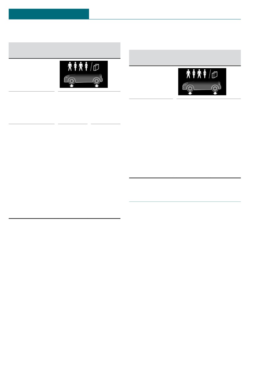
MOBILITY
Wheels and tires
COOPER S
On 3-door models: JOHN COOPER
WORKS
Tire size
Pressure specifica-
tions in bar/PSI
Tire size
Pressure specifications
in bar/PSI
Specifications in
bar/PSI with
Specifications
cold tires
in bar/PSI with
cold tires
195/55 R 16 87
2.9 / 42
2.6 / 38
V A/S
205/45 R 17 88
3.4 / 49
3.0 / 44
195/55 R 16 87
V XL A/S
H M+S
205/45 R 17 88
W XL
205/45 R 17 88
3.2 / 46
2.9 / 42
V XL A/S
205/40 R 18 86
W XL
205/45 R 17 88
W XL
185/50 R 17 86
H XL M+S
205/45 R 17 88
V XL M+S
205/45 R 17 88
V XL M+S
205/40 R 18 86
W XL
175/60 R 16 86
H XL M+S
Tire identification marks
185/50 R 17 86
H XL M+S
Tire size
205/45 R 17 84 V
205: nominal width in mm
45: aspect ratio in %
R: radial tire code
17: rim diameter in inches
84: load rating, not for ZR tires
V: speed rating, before the R on ZR tires
Maximum tire load
Maximum tire load is the maximum permis-
sible weight for which the tire is approved.
Locate the maximum tire load on the tire
sidewall and the Gross Axle Weight Rating
- GAWR - on the certification label on the
driver’s door pillar. Divide the tire load by
1.1. It must be greater than one-half of the
244

Wheels and tires
MOBILITY
vehicle’s Gross Axle Weight Rating -
Uniform Tire Quality Grading
GAWR. Note, front vs. rear GAWR and tire
Quality grades can be found where applica-
loads, respectively.
ble on the tire sidewall between tread
shoulder and maximum section width.
Speed letter
E.g.: Treadwear 200; Traction AA; Tempera-
ture A
Designation Maximum speed
Q
up to 100 mph/160 km/h
DOT Quality Grades
R:
up to 106 mph/170 km/h
Treadwear
Traction AA A B C
S
up to 112 mph/180 km/h
Temperature A B C
T
up to 118 mph/190 km/h
All passenger vehicle tires must conform to
H
up to 131 mph/210 km/h
Federal Safety Requirements in addition to
these grades.
V
up to 150 mph/240 km/h
W
up to 167 mph/270 km/h
Treadwear
Y
up to 186 mph/300 km/h
The treadwear grade is a comparative rating
based on the wear rate of the tire when
tested under controlled conditions on a
Tire Identification Number
specified government test course. E.g., a
DOT-Code: DOT xxxx xxx 0120
tire graded 150 would wear one and one-
xxxx: manufacturer code for the tire brand
half, 1 g, times as well on the government
course as a tire graded 100. The relative
xxx: tire size and tire design
performance of tires depends upon the ac-
0120: tire age
tual conditions of their use, however, and
Tires with DOT codes meet the guidelines
may depart significantly from the norm due
of the U.S. Department of Transportation.
to variations in driving habits, service prac-
tices and differences in road characteristics
Tire age
and climate.
Recommendation
Traction
Regardless of the tire tread, replace tires at
The traction grades, from highest to lowest,
least every 6 years.
are AA, A, B, and C.
Those grades represent the tire's ability to
Manufacture date
stop on wet pavement as measured under
You can find the manufacture date of the
controlled conditions on specified govern-
tire on the tire's sidewall.
ment test surfaces of asphalt and concrete.
A tire marked C may have poor traction per-
Designation
Manufacture date
formance.
DOT … 0120
1st week 2020
The traction grade assigned to this tire is
based on straight-ahead braking traction
tests, and does not include acceleration,
245
MOBILITY
Wheels and tires
cornering, hydroplaning, or peak traction
Tire tread
characteristics.
Summer tires
Temperature
Do not drive with a tire tread of less than
The temperature grades are A, the highest,
0.12 in/3 mm, otherwise there is an in-
B, and C, representing the tire's resistance
creased risk of hydroplaning.
to the generation of heat and its ability to
dissipate heat when tested under controlled
conditions on a specified indoor laboratory
Winter tires
test wheel. Sustained high temperature can
Do not drive with a tire tread of less than
cause the material of the tire to degenerate
0.16 in/4 mm, as such tires are less suitable
and reduce tire life, and excessive tempera-
for winter operation.
ture can lead to sudden tire failure. The
grade C corresponds to a level of perform-
Minimum tread depth
ance which all passenger car tires must
meet under the Federal Motor Vehicle
Safety Standard No. 109. Grades Band A
represent higher levels of performance on
the laboratory test wheel than the minimum
required by law.
Warning
The temperature grade for this tire is es-
tablished for a tire that is properly inflated
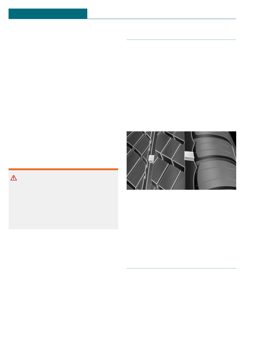
Wear indicators are distributed around the
and not overloaded. Excessive speed, un-
tire's circumference and have the legally re-
derinflation, or excessive loading, either
quired minimum height of 0.063 in-
separately or in combination, can cause
ches/1.6 mm.
heat buildup and possible tire failure.
The positions of the wear indicators are
marked on the tire sidewall with TWI, Tread
RSC - Run-flat tires
Wear Indicator.
Run-flat tires, refer to page 249, are labeled
with a circular symbol containing the let-
ters RSC marked on the sidewall.
Tire damage
M+S
General information
Winter and all-season tires with better cold
Inspect your tires regularly for damage, for-
weather performance than summer tires.
eign objects lodged in the tread, and tread
wear.
Driving over rough or damaged road surfa-
ces, as well as debris, curbs and other obsta-
cles can cause serious damage to wheels,
tires and suspension parts. This is more
246

Wheels and tires
MOBILITY
likely to occur with low-profile tires, which
damage. There is a danger of accidents and
provide less cushioning between the wheel
property damage. If possible, avoid driving
and the road. Be careful to avoid road haz-
over objects or road conditions that may
ards and reduce your speed, especially if
damage tires, or drive over them slowly
your vehicle is equipped with low-profile
and carefully.
tires.
Indications of tire damage or other vehicle
malfunctions:
Changing wheels and tires
- Unusual vibrations.
- Unusual tire or running noises.
Mounting and wheel balancing
- Unusual handling such as a strong ten-
Have mounting and tire and wheel balanc-
dency to pull to the left or right.
ing carried out by a dealer’s service center
Damage can be caused by the following sit-
or another qualified service center or repair
uations, for instance:
shop.
- Driving over curbs.
- Road damage.
Wheel and tire combination
- Tire inflation pressure too low.
General information
- Vehicle overloading.
You can ask the dealer's service center or
- Incorrect tire storage.
another qualified service center or repair
shop about the correct wheel/tire combina-
Safety information
tion and wheel rim versions for the vehicle.
Warning
Safety information
Damaged tires can lose tire inflation pres-
sure, which can lead to loss of vehicle con-
Warning
trol. There is a risk of accident. If tire dam-
Wheels and tires which are not suitable
age is suspected while driving,
for your vehicle can damage parts of the
immediately reduce speed and stop. Have
vehicle, for instance due to contact with
wheels and tires checked. For this pur-
the body due to tolerances despite the
pose, drive carefully to the nearest dealer’s
same official size rating. There is a risk of
service center or another qualified service
an accident. The manufacturer of your ve-
center or repair shop. Have vehicle towed
hicle strongly suggests that you use
or transported as needed. Do not repair
wheels and tires that have been recom-
damaged tires, but have them replaced.
mended by the vehicle manufacturer for
your vehicle type.
Warning
Tires can become damaged by driving over
obstacles, e.g., curbs or road damage, at
high speed. Larger wheels have a smaller
tire cross-section. The smaller the tire
cross-section, the higher the risk of tire
247
MOBILITY
Wheels and tires
Retreaded tires
Warning
Incorrect wheel/tire combinations will
Warning
have a negative impact on the vehicle's
Retreaded tires can have different tire cas-
handling and on the function of a variety
ing structures. With advanced age the
of systems, such as the ABS Antilock Brak-
service life can be limited. There is a risk
ing System or DSC Dynamic Stability Con-
of an accident. The manufacturer of your
trol. There is a risk of accident. To main-
vehicle does not recommend the use of re-
tain good handling and vehicle response,
treaded tires.
use only tires with a single tread configu-
ration from a single manufacturer. The
The manufacturer of the vehicle does not
manufacturer of the vehicle recommends
recommend the use of retreaded tires.
that you use wheels and tires that have
been recommended by the vehicle manu-
facturer for your vehicle type. Following
Winter tires
tire damage, have the original wheel/tire
Winter tires are recommended for operat-
combination remounted on the vehicle as
ing on winter roads.
soon as possible.
Although so-called all-season M+S tires pro-
vide better winter traction than summer
tires, they usually do not provide the same
Recommended tire brands
level of performance as winter tires.
Maximum speed of winter tires
If the maximum speed of the vehicle is
higher than the permissible speed for the
winter tires, then attach a label showing the
permissible maximum speed in the field of
view. The label is available from a dealer's
service center or another qualified service
center or repair shop.
For each tire size, the manufacturer of the
With winter tires mounted, observe and do
vehicle recommends certain tire brands.
not exceed the permissible maximum speed.
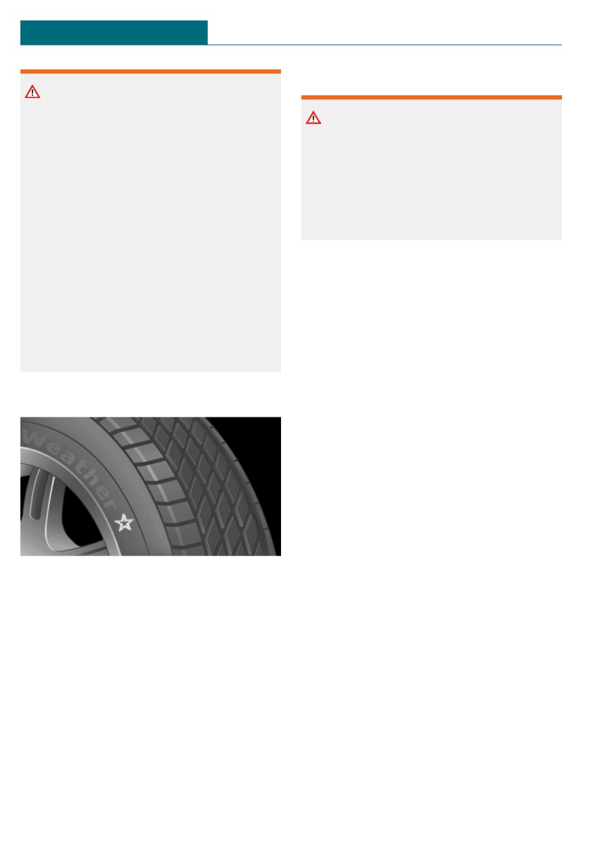
The tire brands can be identified by a star
on the tire sidewall.
Changing runflat tires
For your own safety, use only runflat tires.
New tires
Further information is available from a deal-
er's service center or another qualified serv-
Tire traction is not optimal due to manufac-
ice center or repair shop.
turing circumstances when tires are brand-
new; they achieve their full traction poten-
tial after a break-in time.
Rotating wheels between axles
Drive conservatively for the first
Different wear patterns can occur on the
200 miles/300 km.
front and rear axles depending on individual
driving conditions. The tires can be rotated
in pairs between the axles to achieve even
248
Wheels and tires
MOBILITY
wear. Further information is available from
Safety information
a dealer's service center or another qualified
service center or repair shop. After rotating,
Warning
check the tire pressure and correct, if
needed.
The vehicle handles differently when a
run-flat tire has insufficient or no tire
Storing tires
pressure; for instance, reduced lane stabil-
ity when braking, braking distances are
longer and the self-steering properties will
Tire inflation pressure
change. There is a risk of accident. Drive
Do not exceed the maximum tire inflation
moderately and do not exceed a speed of
pressure indicated on the side wall of the
50 mph/80 km/h.
tire.
Storage
Label
Store wheels and tires in a cool, dry and
dark place.
Always protect tires against all contact with
oil, grease, and solvents.
Do not leave tires in plastic bags.
Remove dirt from wheels or tires.
Run-flat tires
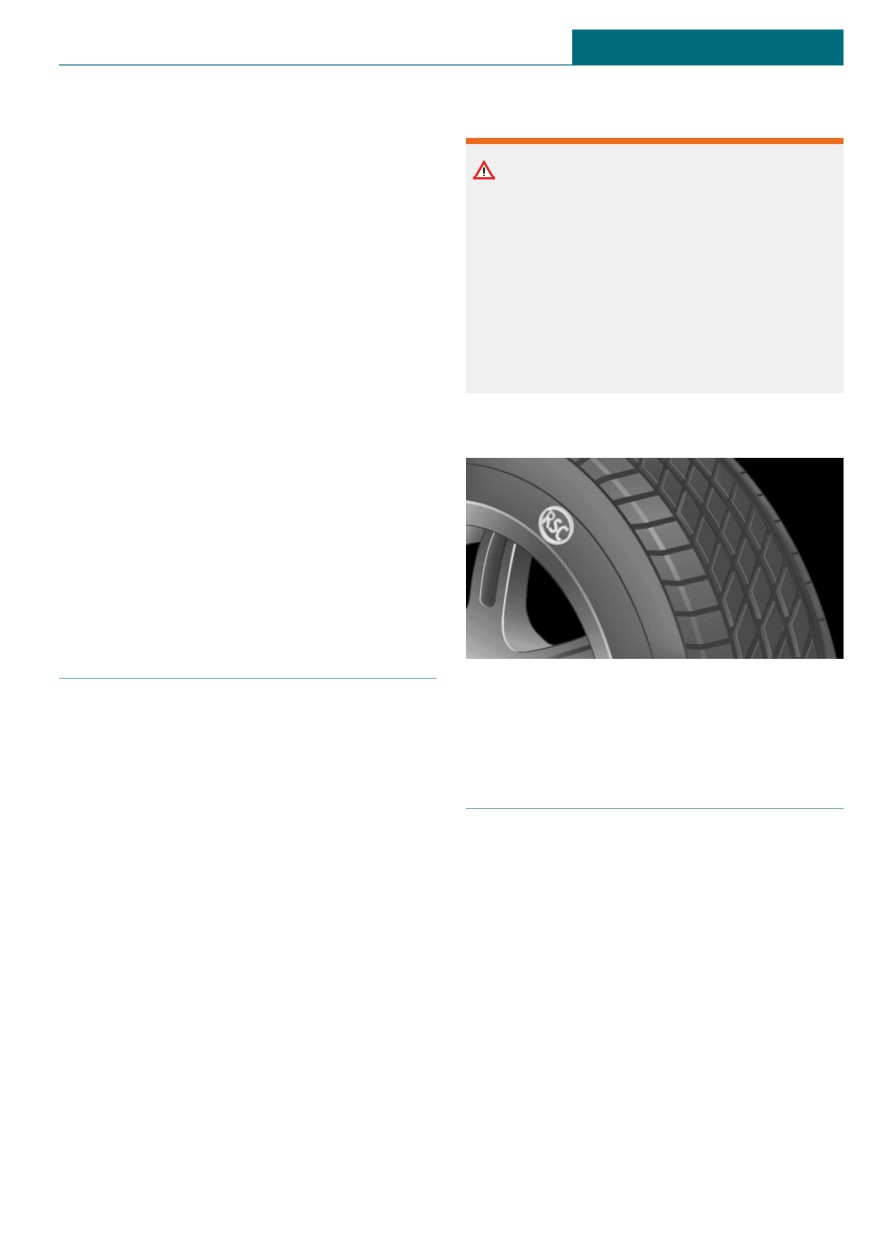
The tires are marked on the tire sidewall
with RSC Run-flat System Component.
Concept
Run-flat tires permit continued driving un-
der restricted conditions even in the event
of a complete loss of tire inflation pressure.
Repairing a flat tire
General information
Safety measures
The wheels are composed of tires that are
- Park the vehicle as far away as possible
self-supporting to a limited degree.
from passing traffic and on solid ground.
The support of the sidewall allows the tire
- Switch on the hazard warning system.
to remain drivable to a restricted degree in
- Secure the vehicle against rolling away
the event of a tire inflation pressure loss.
by setting the parking brake.
Follow the instructions for continued driv-
- Turn the steering wheel until the front
ing with a flat tire.
wheels are in the straight-ahead posi-
tion and engage the steering wheel lock.
- Have all vehicle occupants get out of the
vehicle and ensure that they remain out-
249
MOBILITY
Wheels and tires
side the immediate area in a safe place,
Overview
such as behind a guardrail.
- If necessary, set up a warning triangle
Storage
at an appropriate distance.
The Mobility System is located under the
cargo floor panel.
Mobility System
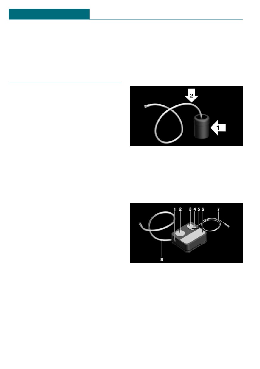
Sealant container
Concept
With the Mobility System, minor tire dam-
age can be sealed temporarily to enable con-
tinued travel. To accomplish this, sealant is
pumped into the tires, which seals the dam-
age from the inside.
General information
-
Follow the instructions on using the
- Sealant container, arrow 1.
Mobility System found on the compres-
- Filling hose, arrow 2.
sor and sealant container.
Observe use-by date on the sealant con-
-
Use of the Mobility System may be inef-
tainer.
fective if the tire puncture measures ap-
prox. 1/8 inches/4 mm or more.
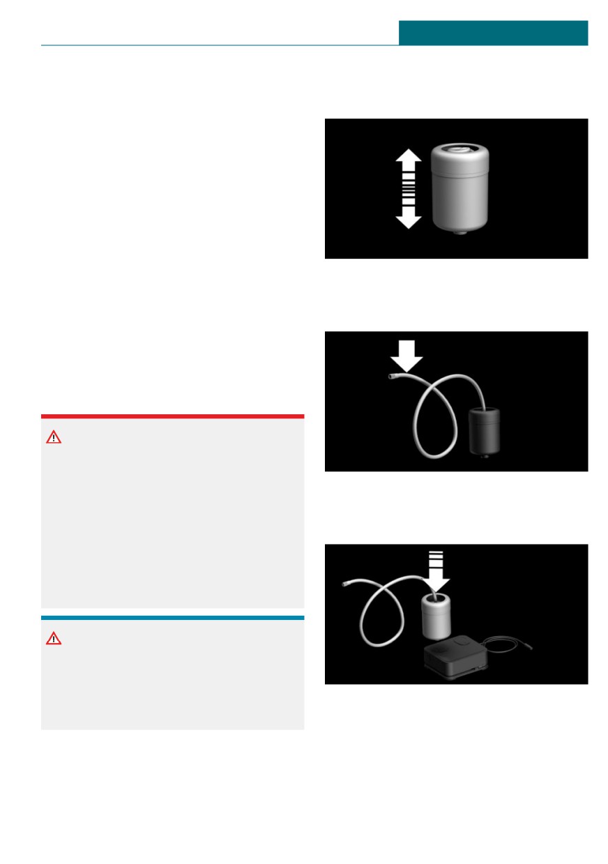
Compressor
-
Contact a dealer's service center or an-
other qualified service center or repair
shop if the tire cannot be made drivable.
-
Do not remove foreign bodies that have
penetrated the tire. Only remove foreign
objects if they are visibly protruding
from the tire.
-
Pull the speed limit sticker off the seal-
ant container and apply it to the steer-
ing wheel.
1
Sealant container unlocking
-
The use of a sealant can damage the
TPM wheel electronics. In this case,
2
Sealant container holder
have the TPM wheel electronics re-
3
Tire pressure gage
placed at the next opportunity.
4
Reduce tire inflation pressure button
-
The compressor can be used to check
5
On/off switch
the tire inflation pressure.
6
Compressor
7
Connector/cable for socket
8
Connection hose
250
Wheels and tires
MOBILITY
Safety measures
Filling
- Park the vehicle as far away as possible
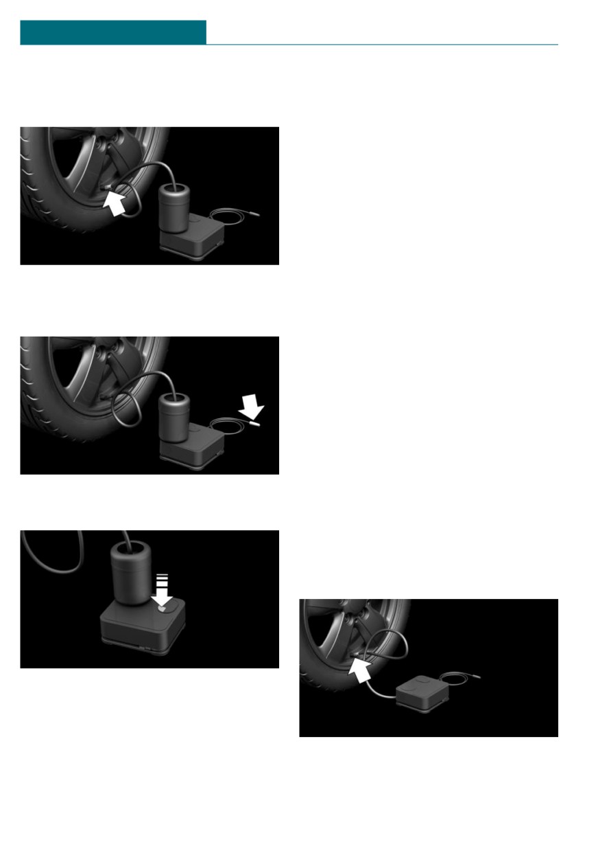
1.
Shake the sealant container.
from passing traffic and on solid ground.
- Switch on the hazard warning system.
- Secure the vehicle against rolling away
by setting the parking brake.
- Turn the steering wheel until the front
wheels are in the straight-ahead posi-
tion and engage the steering wheel lock.
- Have all vehicle occupants get out of the
vehicle and ensure that they remain out-
side the immediate area in a safe place,
2.
Pull filling hose completely out of the
such as behind a guardrail.
cover of the sealant container. Do not
- If necessary, set up a warning triangle
kink the hose.
at an appropriate distance.
Filling the tire with sealant
Safety information
DANGER
If the exhaust pipe is blocked or ventila-
tion is insufficient, harmful exhaust gases
can enter into the vehicle. The exhaust
3.
Slide the sealant container into the
gases contain pollutants which are color-
holder on the compressor housing, en-
less and odorless. In enclosed areas, ex-
suring that it engages audibly.
haust gases can also accumulate outside of
the vehicle. There is danger to life. Keep
the exhaust pipe free and ensure sufficient
ventilation.
NOTICE
The compressor can overheat during ex-
tended operation. There is a risk of dam-
age to property. Do not run the compres-
sor for more than 10 minutes.
251
MOBILITY
Wheels and tires
4.
Screw the filling hose of the sealant con-
Checking and adjusting the tire
tainer onto the tire valve of the non-
inflation pressure
working wheel.
Checking
1. Switch off the compressor.
2. Read the tire inflation pressure on the
tire pressure gage.
To continue the trip, a tire inflation pres-
sure of at least 2 bar must be reached.
Removing and stowing the sealant
container
5.
With the compressor switched off, in-
1. Unscrew the filling hose of the sealant
sert the plug into the power socket in-
container from the tire valve.
side the vehicle.
2. Press the red unlocking device.
3. Remove the sealant container from the
compressor.
4. Wrap and store the sealant container in
suitable material to avoid dirtying the
cargo area.
Minimum tire inflation pressure is not
reached
1. Pull the connector out of the power
6.
With the ignition switched on or the en-
socket inside the vehicle.
gine running, switch on the compressor.
2. Drive 33 ft/10 m forward and back to
distribute the sealant in the tire.
3. Screw the connection hose of the com-
pressor directly onto the tire valve stem.
Let the compressor run for max. 10 minutes
to fill the tire with sealant and achieve a
tire inflation pressure of approx. 2.5 bar.
While the tire is being filled with sealant,
the tire inflation pressure may sporadically
reach approx. 5 bar. Do not switch off the
compressor at this point.
252
Wheels and tires
MOBILITY
4. Insert the connector into the power
Adjustment
socket inside the vehicle.
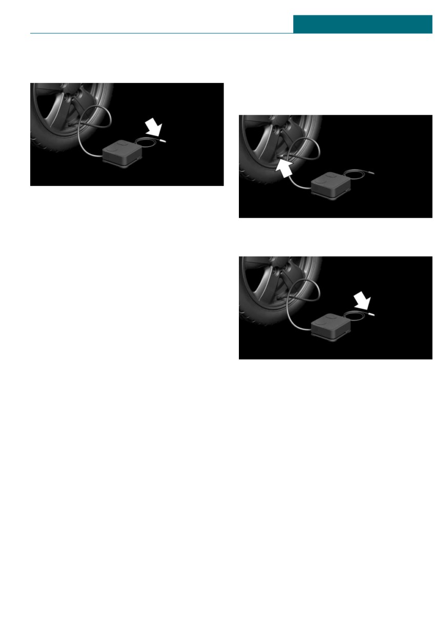
1. Stop at a suitable location.
2. Screw the connection hose of the com-
pressor directly onto the tire valve stem.
5. With the ignition switched on or the en-
gine running, switch on the compressor.
If a tire inflation pressure of at least
3.
Insert the connector into the power
2 bar cannot be reached, contact your
socket inside the vehicle.
dealer's service center or another quali-
fied service center or repair shop.
If a tire inflation pressure of at least
2 bar is reached, see Minimum tire infla-
tion pressure is reached.
6. Unscrew the connection hose of the
compressor from the tire valve.
7. Pull the connector out of the power
socket inside the vehicle.
8. Stow the Mobility System in the vehicle.
4.
Correct the tire inflation pressure to at
least 2.0 bar.
Minimum tire inflation pressure is
- Increase tire inflation pressure: with
reached
the ignition switched on or the en-
1. Unscrew the connection hose of the
gine running, switch on the com-
compressor from the tire valve.
pressor.
2. Pull the connector out of the power
- Reduce tire inflation pressure: press
socket inside the vehicle.
the button on the compressor.
3. Stow the Mobility System in the vehicle.
5.
Unscrew the connection hose of the
compressor from the tire valve.
4. Immediately drive approx.
5 miles/10 km to ensure that the sealant
6.
Pull the connector out of the power
is evenly distributed in the tire.
socket inside the vehicle.
Do not exceed a speed of
7.
Stow the Mobility System in the vehicle.
50 mph/80 km/h.
If possible, do not drive at speeds less
Continuing the trip
than 12 mph/20 km/h.
Do not exceed the maximum permissible
speed of 50 mph/80 km/h.
253

MOBILITY
Wheels and tires
Reinitialize the Flat Tire Monitor, refer to
page 158.
Warning
Reset the Tire Pressure Monitor, refer to
Insufficiently tight snow chains may dam-
page 153.
age tires and vehicle components. There
Replace the nonworking tire and the sealant
may be a risk of accident or risk of damage
container of the Mobility System promptly.
to property. Make sure that the snow
chains are always sufficiently tight. Re-
tighten as needed according to the snow
chain manufacturer's instructions.
Snow chains
General information
Fine-link snow chains
The manufacturer of the vehicle has deter-
The manufacturer of the vehicle recom-
mined certain wheels and tires to be suita-
mends the use of fine-link snow chains. Cer-
ble for operation on the vehicle.
tain types of fine-link snow chains have
Follow the snow chain manufacturer's in-
been tested by the manufacturer of the ve-
structions.
hicle and recommended as road-safe and
suitable.
Do not initialize the Flat Tire Monitor after
mounting snow chains, as doing so may re-
Information regarding suitable snow chains
sult in incorrect readings.
is available from a dealer’s service center or
another qualified service center or repair
Do not reset the Tire Pressure Monitor TPM
shop.
after mounting snow chains, as doing so
may result in incorrect readings.
Use
When driving with snow chains, briefly ac-
Use only in pairs on the front wheels, equip-
tivate Dynamic Traction Control DTC, if
ped with the tires of the following size:
needed.
-
175/65 R 15.
Safety information
-
175/60 R 16.
-
185/50 R 17.
Warning
John Cooper Works:
With the mounting of snow chains on un-
185/50 R 17.
suitable tires, the snow chains can come
into contact with vehicle parts. There may
Maximum speed with snow chains
be a risk of accident or risk of damage to
Do not exceed a speed of 30 mph/50 km/h
property. Only mount snow chains on tires
when using snow chains.
that are designated by their manufacturer
as suitable for the use of snow chains.
Changing wheels/tires
General information
When using run-flat tires or a flat tire kit, a
wheel does not always need to be changed
254

Wheels and tires
MOBILITY
immediately when there is a loss of tire in-
flation pressure due to a flat tire.
Warning
If needed, the tools for changing wheels are
On soft, uneven or slippery ground, for ex-
available as accessories from a dealer’s
ample snow, ice, tiles, etc., the vehicle jack
service center or another qualified service
can slip away. There is a risk of injury. If
center or repair shop.
possible, change the wheel on a flat, solid,
and slip-resistant surface.
Safety information
Warning
DANGER
The vehicle jack is optimized for lifting
The vehicle jack is only provided for short-
the vehicle and for the jacking points on
term lifting of the vehicle for wheel
the vehicle only. There is a risk of injury.
changes. Even if all safety measures are
Do not lift any other vehicle or cargo using
observed, there is a risk of the raised vehi-
the vehicle jack.
cle falling, if the vehicle jack tips over.
There is a risk of injuries or danger to life.
If the vehicle is raised, do not lie under the
vehicle and do not start the engine.
Warning
When the vehicle jack is not inserted into
the jacking point provided for this pur-
DANGER
pose, the vehicle may be damaged or the
vehicle jack may slip when it is being
Supports such as wooden blocks under the
cranked up. There is a risk of injury or risk
vehicle jack reduce the capacity of the ve-
of damage to property. When cranking up
hicle jack to bear weight. They have the
the vehicle jack, ensure that it is inserted
potential to exert too much strain on the
in the jacking point next to the wheel
vehicle jack, causing it to tip over and the
housing.
vehicle to fall. There is a risk of injuries or
danger to life. Do not place supports under
the vehicle jack.
Warning
A vehicle that is raised on a vehicle jack
Warning
may fall off of the jack if lateral forces are
exerted on it. There is a risk of injury and
The jack, issued by the vehicle manufac-
risk of damage to property. While the ve-
turer, is provided in order to perform a
hicle is raised, do not exert lateral forces
wheel change in the event of a breakdown.
on the vehicle or pull abruptly on the vehi-
The jack is not designed for frequent use;
cle. Have a stuck wheel removed by a deal-
for example, changing from summer to
er’s service center or another qualified
winter tires. Using the jack frequently may
service center or repair shop.
cause it to become jammed or damaged.
There is a risk of injury and risk of damage
to property. Only use the jack to attach an
emergency or spare wheel in the event of
a breakdown.
255
MOBILITY
Wheels and tires
Securing the vehicle against rolling
Lug bolt lock
General information
Concept
The vehicle manufacturer recommends to
The wheel lug bolts have a special coding.
additionally secure the vehicle against roll-
The lug bolts can only be released with the
ing away when changing a wheel.
adapter which matches the coding.
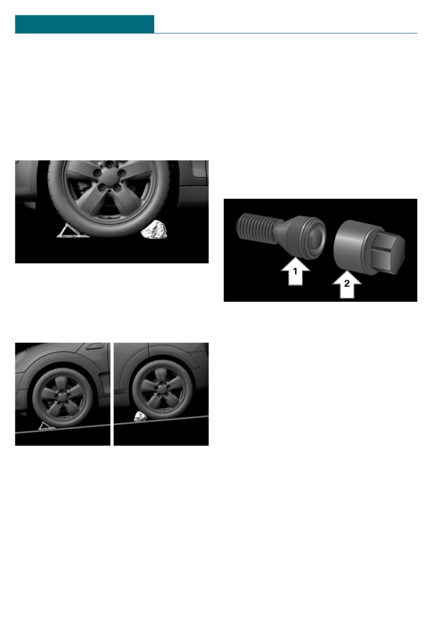
On a level surface
Overview
The adapter of the lug bolt lock is located in
the onboard vehicle tool kit, refer to
page 272.
Place wheel chocks or other suitable objects
in front and behind the wheel that is diago-
nal to the wheel to be changed.
- Lug bolt, arrow 1.
On a slight downhill gradient
- Adapter, arrow 2.
Unscrewing
1. Attach the adapter to the lug bolt.
2. Unscrew the lug bolt.
3. Remove the adapter after unscrewing
the lug bolt.
Screwing on
If you need to change a wheel on a slight
1. Attach the adapter to the lug bolt. If
downhill grade, place chocks and other suit-
necessary, turn the adapter until it fits
able objects, for instance a rock, under the
on the lug bolt.
wheels of both the front and rear axles
2. Screw on the lug bolt. The tightening
against the rolling direction.
torque is 140 Nm.
3. Remove the adapter and stow it after
screwing on the lug bolt.
Preparing the vehicle
- Park the vehicle on solid and non-slip
ground at a safe distance from traffic.
256
Wheels and tires
MOBILITY
– Switch on the hazard warning system.
Jacking up the vehicle
– Set the parking brake.
- Engage a gear or move the selector lever
Warning
to position P.
Hands and fingers can be jammed when
- As soon as permitted by the traffic flow,
using the vehicle jack. There is a risk of
have all vehicle occupants get out of the
injury. Comply with the described hand
vehicle and ensure that they remain out-
position and do not change this position
side the immediate area in a safe place,
while using the vehicle jack.
such as behind a guardrail.
- Depending on the vehicle equipment,
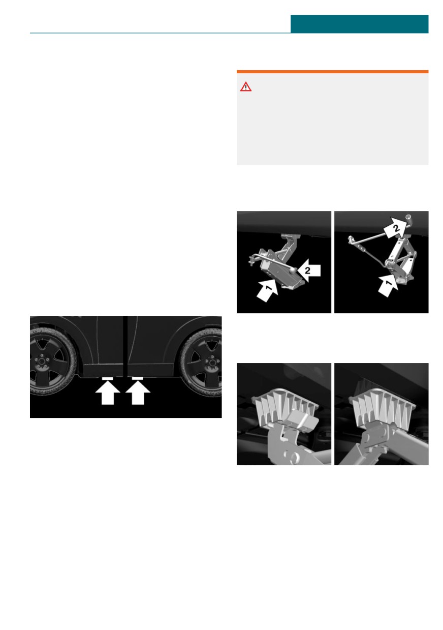
1. Hold the vehicle jack with one hand, ar-
get wheel change tools and, if necessary,
row 1, and grasp the vehicle jack crank
the emergency wheel from the vehicle.
or lever with your other hand, arrow 2.
- If necessary, set up a warning triangle
or portable hazard warning light at an
appropriate distance.
- Secure the vehicle additionally against
rolling.
- Loosen the lug bolts a half turn.
Jacking points for the vehicle jack
2. Insert the vehicle jack into the rectan-
gular recess of the jacking point closest
to the wheel to be changed.
The jacking points for the vehicle jack are
located at the marked positions.
257
MOBILITY
Wheels and tires
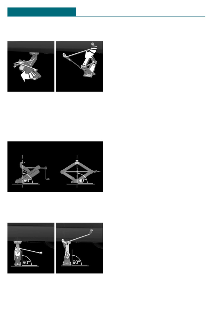
3.
Extend the vehicle jack by turning the
ground and the relevant wheel is maxi-
vehicle jack crank or lever clockwise.
mum 1.2 inches/3 cm above ground.
Mounting a wheel
Mount one emergency wheel only, as re-
quired.
1. Unscrew the lug bolts.
2. Remove the wheel.
3. Put the new wheel or emergency wheel
on and screw in at least two lug bolts in
a crosswise pattern until hand-tight.
4.
Take your hand away from the vehicle
jack as soon as the vehicle jack is under
If non-original light-alloy wheels of the
load and continue turning the vehicle
vehicle manufacturer are mounted, the
jack crank or lever with one hand.
accompanying lug bolts may have to be
used as well.
5.
Make sure that the vehicle jack foot
stands vertically and at a right angle be-
4. Hand-tighten the remaining lug bolts
neath the jacking point.
and tighten all lug bolts well in a cross-
wise pattern.
5. Turn the vehicle jack crank counter-
clockwise to retract the vehicle jack and
lower the vehicle.
6. Remove the vehicle jack and stow it se-
curely.
After the wheel change
1. Tighten the lug bolts crosswise. The
6.
Make sure that the vehicle jack foot
tightening torque is 101 lbs ft/140 Nm.
stands vertically and perpendicularly be-
2. Stow the nonworking wheel in the cargo
neath the jacking point after extending
area, if necessary.
the vehicle jack.
The nonworking wheel cannot be stored
under the cargo floor panel because of
its size.
3. Check tire inflation pressure at the next
opportunity and correct as needed.
4. Reinitialize the Flat Tire Monitor.
Reset the Tire Pressure Monitor TPM.
5. Check to make sure the lug bolts are
tight with a calibrated torque wrench.
7.
Crank the vehicle up, until the vehicle
6. Have the damaged tire replaced at the
jack is with the entire surface on the
nearest dealer's service center or an-
258
Wheels and tires
MOBILITY
other qualified service center or repair
Removing the emergency wheel
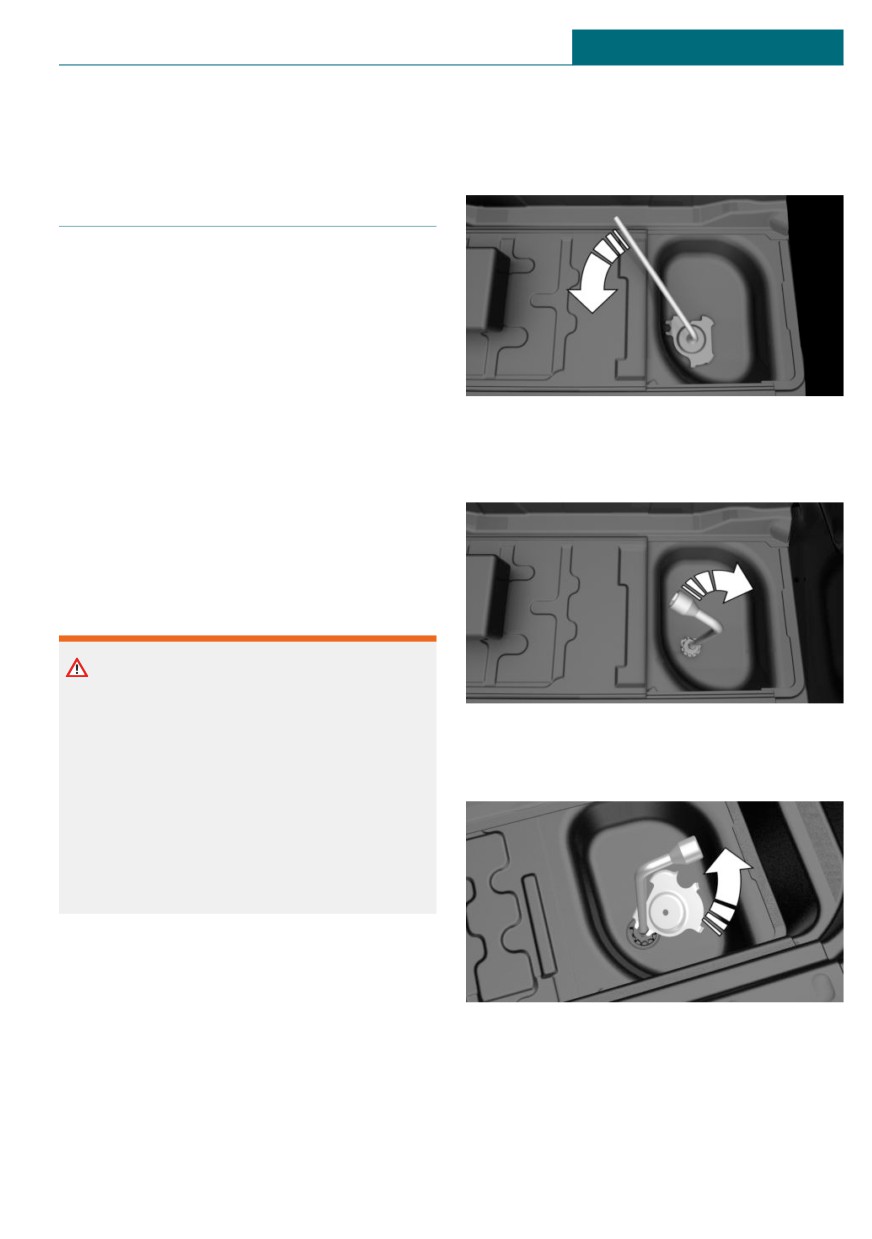
shop.
1.
Loosen the nut using the wheel wrench
from the onboard vehicle tool kit.
Emergency wheel
Concept
In the event of a flat tire, the emergency
wheel can be used in place of the wheel
with the defective tire. The emergency
wheel is only intended for temporary use
until the defective tire/wheel has been re-
placed.
2.
Remove the retaining plate.
3.
Screw wheel lug wrench onto the thread
General information
and hold in place with one hand.
Mount one emergency wheel only.
Also check the tire inflation pressure of the
emergency wheel in the cargo area regu-
larly, and correct it as needed.
Safety information
Warning
The emergency wheel has particular di-
mensions. When driving with an emer-
4.
Unlock the locking hexagon of the emer-
gency wheel, changed driving properties
gency wheel well using the hexagon at-
may occur, for instance reduced lane sta-
tached to retaining plate.
bility when braking, longer braking dis-
tance, and changed self-steering proper-
ties in the limit area. There is a risk of
accident. Drive moderately and do not ex-
ceed a speed of 50 mph/80 km/h.
Overview
The emergency wheel is housed in a well on
the underbody of the vehicle. The screw
connection of the emergency wheel is under
5. Lower the emergency wheel with the
the cargo floor panel, on the floor of the
wheel wrench.
storage compartment for the onboard vehi-
6. Unscrewing the wheel wrench
cle tool kit.
7. Pull out the well with emergency wheel
The wheel change tools are under the cargo
under the vehicle toward the rear.
floor panel.
259
MOBILITY
Wheels and tires
8. Remove the spacer and emergency
wheel from the well.
9. Stow the well and spacer in the vehicle.
Replacing the tires
1. Have the damaged tire replaced.
2. Replace the emergency wheel with the
new wheel.
Installing the emergency wheel
Have the emergency wheel installed back
into the vehicle by a dealer’s service center
or another qualified service center or repair
shop.
260
Engine compartment
MOBILITY
Engine compartment
in your vehicle, e.g., due to the selected op-
Vehicle features and options
tions or country versions. This also applies
to safety-related functions and systems.
This chapter describes all standard, country-
When using these functions and systems,
specific and optional features offered with
the applicable laws and regulations must be
the series. It also describes features and
observed.
functions that are not necessarily available
Overview
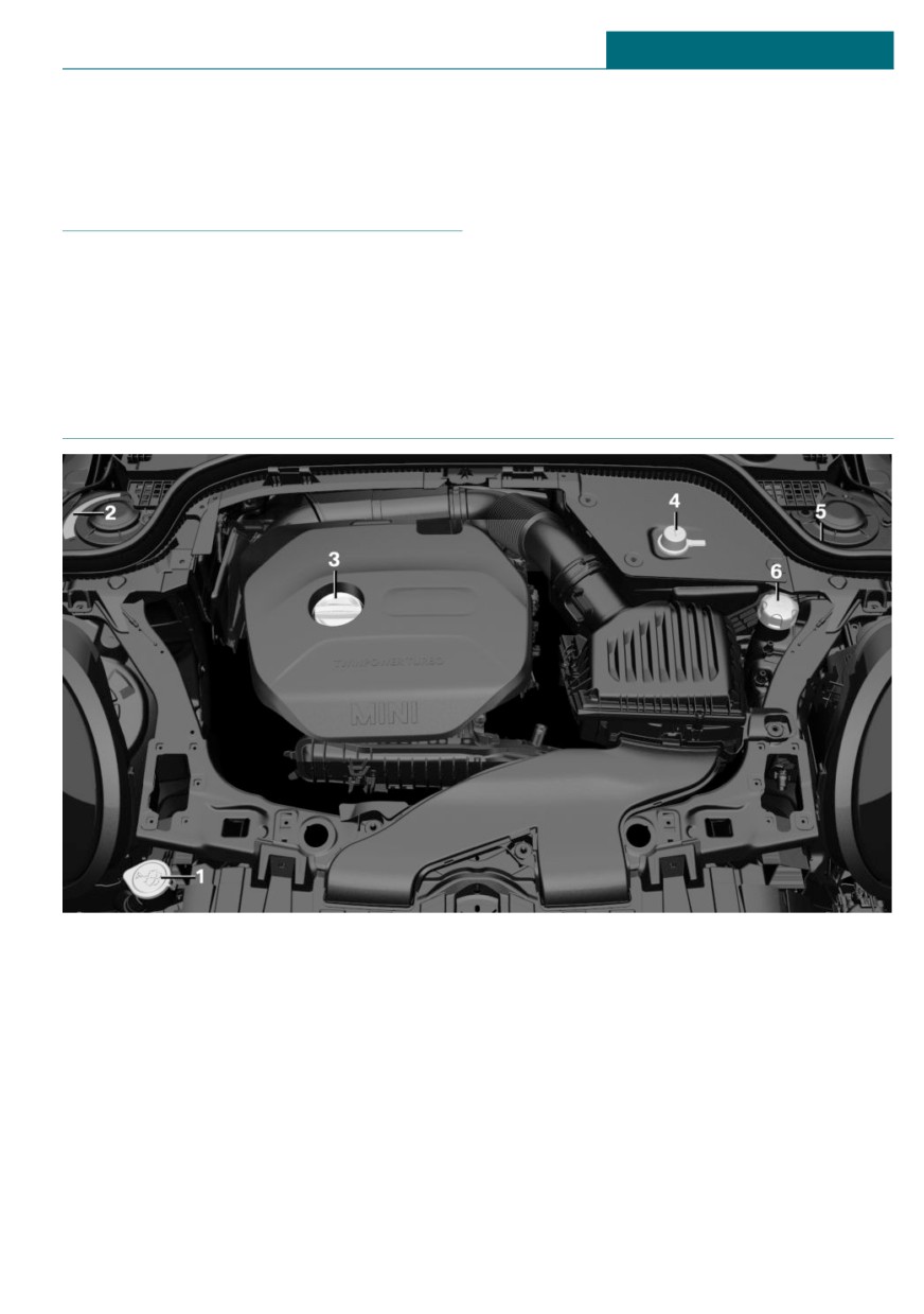
1
Filler neck for washer fluid
4
Jump-starting, positive terminal
2
Vehicle identification number
5
Jump-starting, negative terminal
3
Oil filler neck
6
Coolant reservoir
261
MOBILITY
Engine compartment
Hood
Warning
Body parts can be jammed when opening
Safety information
and closing the hood. There is a risk of in-
jury. Make sure that the area of movement
Warning
of the hood is clear during opening and
closing.
Improperly executed work in the engine
compartment can damage vehicle compo-
nents and impair vehicle functions. There
is a risk of an accident and damage to
NOTICE
property. Have work in the engine com-
Folded-away wipers can be jammed when
partment performed by a dealer’s service
the hood is opened. There is a risk of dam-
center or another qualified service center
age to property. Make sure that the wipers
or repair shop.
with the wiper blades mounted are folded
down onto the windshield before opening
the hood.
Warning
The engine compartment accommodates
moving components. Certain components
NOTICE
in the engine compartment can also move
When the hood is closed, it must engage
with the vehicle switched off, for instance
on both sides. Pressing again can damage
the radiator fan. There is a risk of injury.
the hood. There is a risk of damage to
Do not reach into the area of moving parts.
property. Open the hood again and then
Keep articles of clothing and hair away
close it energetically. Avoid pressing
from moving parts.
again.
Warning
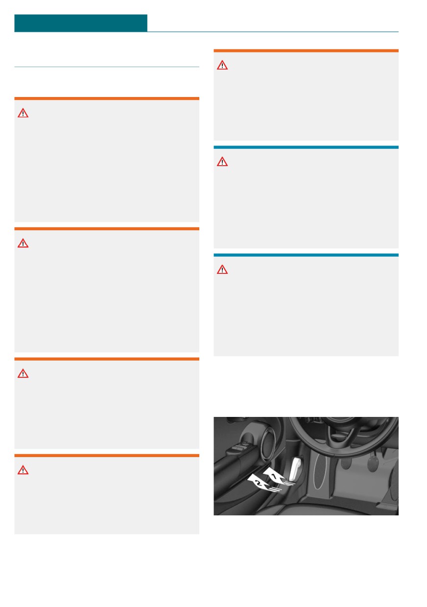
Opening the hood
There are protruding parts, for instance
1. Pull lever, arrow 1.
locking hook, on the inside of the hood.
Hood is unlocked.
There is a risk of injury. If the hood is
open, pay attention to protruding parts
and keep clear of these areas.
Warning
An incorrectly locked hood can open while
driving and restrict visibility. There is a
risk of accident. Stop immediately and cor-
rectly close the hood.
2. After the lever is released, pull the lever
again, arrow 2.
Hood can be opened.
262
Engine compartment
MOBILITY
Indicator/warning lights
When the hood is opened, a Check Control
message is displayed.
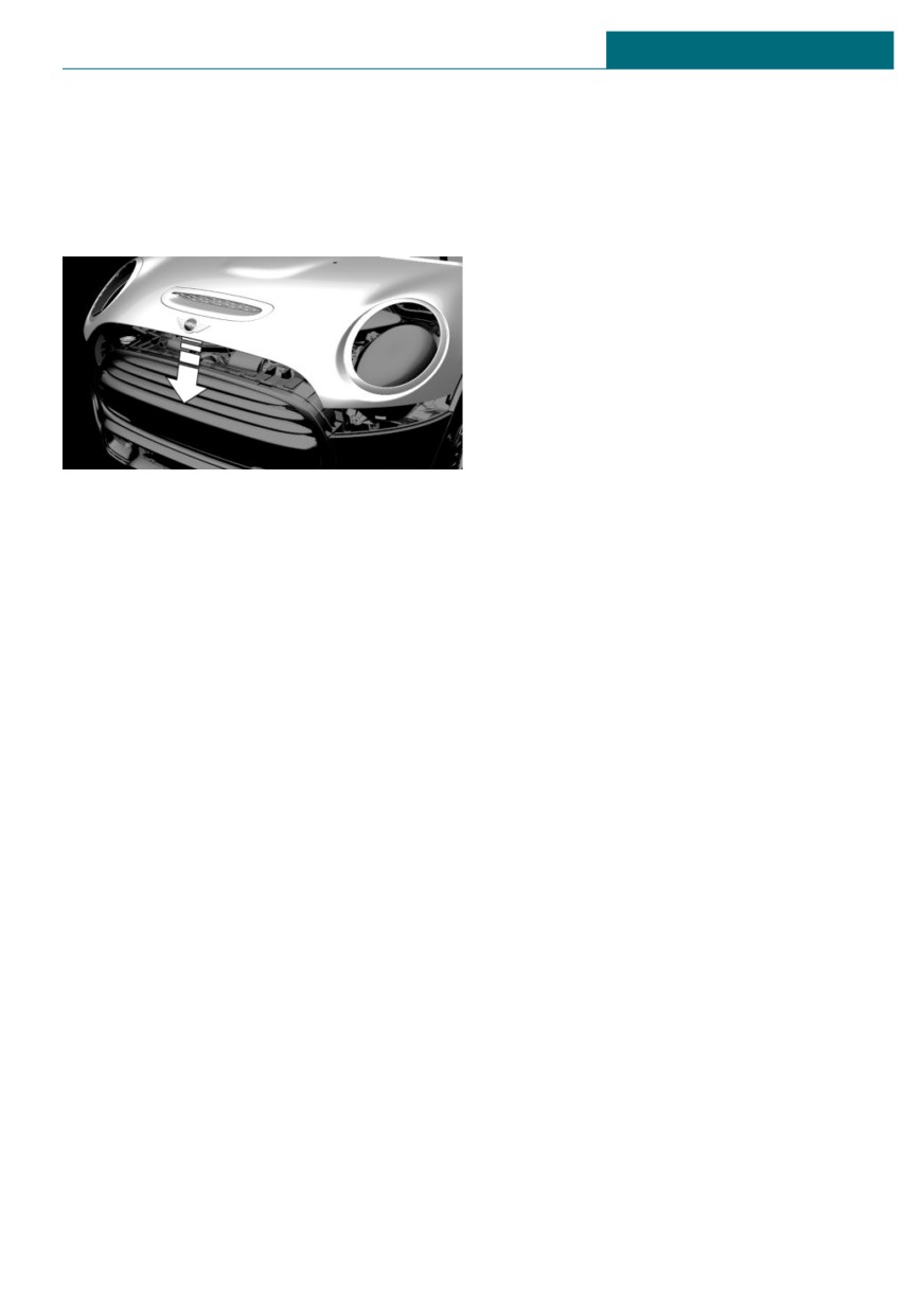
Closing the hood
Energetically close the hood from approx.
20 in/50 cm.
The hood must engage on both sides.
263
MOBILITY
Engine oil
Engine oil
Vehicle features and options
Safety information
This chapter describes all standard, country-
specific and optional features offered with
NOTICE
the series. It also describes features and
An engine oil level that is too low causes
functions that are not necessarily available
engine damage. There is a risk of damage
in your vehicle, e.g., due to the selected op-
to property. Immediately add engine oil.
tions or country versions. This also applies
to safety-related functions and systems.
When using these functions and systems,
NOTICE
the applicable laws and regulations must be
observed.
Too much engine oil can damage the en-
gine or the catalytic converter. There is a
risk of damage to property. Do not add too
General information
much engine oil. When too much engine
oil is added, have the engine oil level cor-
rected by a dealer’s service center or an-
The engine oil consumption is dependent on
other qualified service center or repair
your driving style and driving conditions.
shop.
Therefore, regularly check the engine oil
level after refueling by taking a detailed
measurement.
The engine oil consumption can increase in
Electronic oil measurement
the following situations, for instance:
- Sporty driving style.
General information
- Break-in of the engine.
The electronic oil measurement has two
- Idling of the engine.
measuring principles:
- With use of engine oil types that are
- Monitoring.
classified as not suitable.
- Detailed measurement.
Different Check Control messages appear,
When making frequent short-distance trips
depending on the engine oil level.
or using a dynamic driving style, for in-
stance when taking curves aggressively,
regularly perform a detailed measurement.
Monitoring
Concept
The engine oil level is monitored electroni-
cally while driving and can be shown on the
Control Display.
264
Engine oil
MOBILITY
If the engine oil level is outside its permis-
– Manual transmission: shift lever in neu-
sible operating range, a Check Control mes-
tral position, clutch and accelerator ped-
sage is displayed.
als not depressed.
A red indicator light indicates that
- Steptronic transmission: selector lever
the engine oil pressure is too low.
in selector lever position N or P and ac-
celerator pedal not depressed.
- Engine is running and is at operating
Functional requirements
temperature.
A current measured value is available after
approx. 30 minutes of normal driving.
Performing a detailed measurement
Via the Central Information Display (CID):
Displaying the engine oil level
1.
"My MINI"
Via the Central Information Display (CID):
2. "Vehicle status"
1.
"My MINI"
3.
"Engine oil level"
2. "Vehicle status"
4. "Measure engine oil level"
3.
"Engine oil level"
5. "Start measurement"
The engine oil level is displayed.
The engine oil level is checked and dis-
played via a scale.
System limits
When making frequent short-distance trips
or using a dynamic driving style, it may not
Adding engine oil
be possible to calculate a measured value.
In this case, the measured value for the last,
sufficiently long trip is displayed.
General information
Only add engine oil when the message is
Detailed measurement
displayed in the instrument cluster. The
quantity to be added is indicated in the
Concept
message displayed in the instrument clus-
The engine oil level is checked when the ve-
ter.
hicle is stationary and displayed via a scale.
Only add suitable types of engine oil, refer
If the engine oil level is outside its permis-
to page 267.
sible operating range, a Check Control mes-
Safely park the vehicle and switch off the
sage is displayed.
ignition before adding engine oil.
Take care not to add too much engine oil.
General information
During the measurement, the idle speed is
increased somewhat.
Functional requirements
- Vehicle is parked in a horizontal posi-
tion.
265
MOBILITY
Engine oil
Safety information
Adding engine oil
1. Open the hood, refer to page 262.
Warning
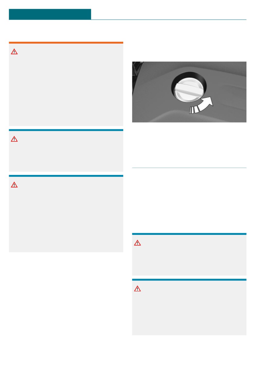
2. Open the lid counterclockwise.
Operating materials, for instance oils,
greases, coolants, fuels, can contain harm-
ful ingredients. There is a risk of injuries
or danger to life. Follow the instructions
on the containers. Avoid the contact of ar-
ticles of clothing, skin or eyes with operat-
ing materials. Do not refill operating mate-
rials into different bottles. Store operating
materials out of reach of children.
3. Add engine oil.
NOTICE
4. Close the lid.
An engine oil level that is too low causes
engine damage. There is a risk of damage
to property. Immediately add engine oil.
Engine oil types to add
General information
NOTICE
The engine oil quality is critical for the life
Too much engine oil can damage the en-
of the engine.
gine or the catalytic converter. There is a
Only add the types of engine oil which are
risk of damage to property. Do not add too
listed.
much engine oil. When too much engine
oil is added, have the engine oil level cor-
Safety information
rected by a dealer’s service center or an-
other qualified service center or repair
shop.
NOTICE
Oil additives can damage the engine.
There is a risk of damage to property. Do
Overview
not use oil additives.
The oil filler neck is located in the engine
compartment, refer to page 261.
NOTICE
Incorrect engine oil can cause malfunc-
tions in the engine or damage it. There is a
risk of damage to property. When select-
ing an engine oil, make sure that the en-
gine oil has the correct oil rating.
266
Engine oil
MOBILITY
Suitable engine oil types
Engine oil change
Add engine oils that meet the following oil
rating standards:
NOTICE
Gasoline engine
Engine oil that is not changed in timely
BMW Longlife-01 FE.
fashion can cause increased engine wear
BMW Longlife-14 FE+.
and thus engine damage. There is a risk of
damage to property. It is recommended
BMW Longlife-17 FE+.
that you do not exceed the service inter-
vals indicated in the vehicle.
Alternative engine oil types
The vehicle manufacturer recommends that
If an engine oil suitable for continuous use
you have a dealer's service center or an-
is not available, up to 1 US quart/liter of an
other qualified service center or repair shop
engine oil with the following oil rating can
change the engine oil.
be added:
Oil rating
API SL.
API SM.
API SN.
Viscosity grades
When selecting an engine oil, make sure
that the engine oil belongs to one of the fol-
lowing viscosity grades:
Viscosity grades
SAE 0W-20.
SAE 0W-30.
More information about suitable oil ratings
and viscosity grades of engine oils can be
requested from a dealer’s service center or
another qualified service center or repair
shop.
267
MOBILITY
Coolant
Coolant
Vehicle features and options
Warning
Additives are harmful and incorrect addi-
This chapter describes all standard, country-
tives can damage the engine. There is a
specific and optional features offered with
risk of injury and risk of damage to prop-
the series. It also describes features and
erty. Do not allow additives to come into
functions that are not necessarily available
contact with skin, eyes or articles of cloth-
in your vehicle, e.g., due to the selected op-
ing. Use suitable additives only.
tions or country versions. This also applies
to safety-related functions and systems.
When using these functions and systems,
the applicable laws and regulations must be
Coolant level
observed.
Checking
General information
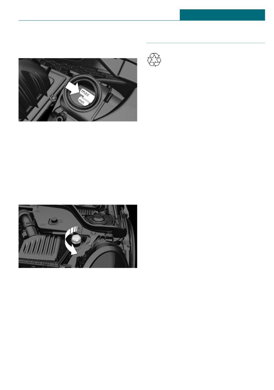
There are yellow Min and Max marks in the
coolant reservoir.
Coolant consists of water and additives.
1. Let the engine cool.
Not all commercially available additives are
2. Open the hood, refer to page 262.
suitable for the vehicle. Do not mix addi-
tives of different colors. Observe the water -
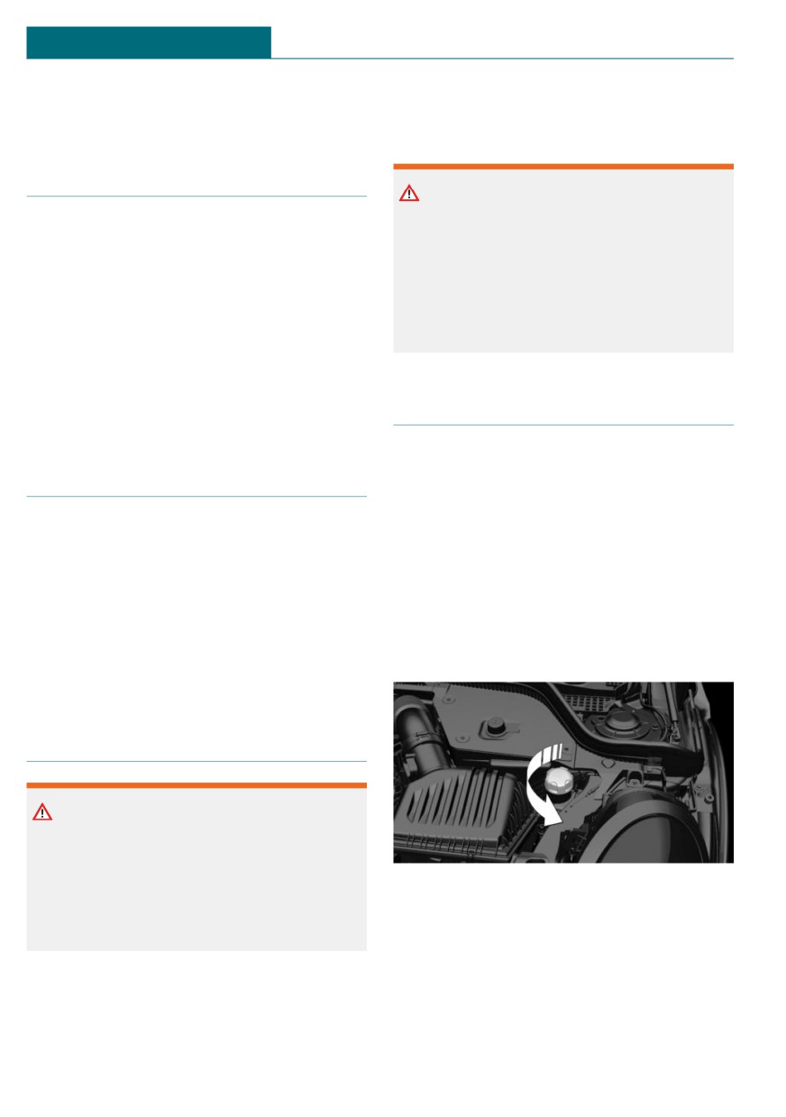
3. Turn the lid of the coolant reservoir
additive mixing ratio of 50:50. Information
slightly counterclockwise to allow any
about suitable additives is available from a
excess pressure to dissipate, then open
dealer’s service center or another qualified
it.
service center or repair shop.
Safety information
Warning
With the engine hot and the cooling sys-
tem open, coolant can escape and lead to
scalding. There is a risk of injury. Only
4. Open the coolant reservoir lid.
open the cooling system with the engine
cooled down.
268
Coolant
MOBILITY
5. The coolant level is correct if it lies be-
Disposal
tween the minimum and maximum
marks in the filler neck.
Comply with the relevant environ-
mental protection regulations when
disposing of coolant and coolant ad-
ditives.
6. Close the lid.
Adding coolant
1. Let the engine cool.
2. Open the hood, refer to page 262.
3. Turn the lid of the coolant reservoir
slightly counterclockwise to allow any
excess pressure to dissipate, then open
it.
4. Open the coolant reservoir lid.
5. If the coolant is low, slowly add coolant
up to the specified level; do not overfill.
6. Close the lid.
7. Have the cause of the coolant loss elimi-
nated as soon as possible.
269

MOBILITY
Maintenance
Maintenance
Vehicle features and options
General information
Information on service notifications, refer
This chapter describes all standard, country-
to page 129, can be displayed on the Control
specific and optional features offered with
Display.
the series. It also describes features and
functions that are not necessarily available
Service data in the vehicle key
in your vehicle, e.g., due to the selected op-
Information on the service notifications is
tions or country versions. This also applies
continuously stored in the vehicle key. The
to safety-related functions and systems.
service center can read this data out and
When using these functions and systems,
suggest a maintenance scope for the vehi-
the applicable laws and regulations must be
cle.
observed.
Therefore, hand the service advisor the ve-
hicle key with which the vehicle was driven
most recently.
MINI maintenance system
Storage periods
The maintenance system provides service
Storage periods during which the vehicle
notifications and thereby provides support
battery was disconnected are not taken into
in maintaining road safety and the opera-
account.
tional reliability of the vehicle.
If this occurs, have a dealer's service center
In some cases, scopes and intervals of the
or another qualified service center or repair
maintenance system may vary according to
shop update the time-dependent mainte-
the country version. Replacement work,
nance procedures, such as checking brake
spare parts, fuels and lubricants, and wear
fluid and, if necessary, changing the engine
materials are calculated separately. Further
oil and the microfilter/activated-charcoal
information is available from a dealer's serv-
filter.
ice center or another qualified service cen-
ter or repair shop.
Maintenance Manual and
Condition Based Service CBS
Service and Warranty Infor-
mation Booklet for US models
Concept
and Warranty and Service
Sensors and special algorithms take into ac-
Guide Booklet for Canadian
count the driving conditions of the vehicle.
models
CBS uses these to calculate the need for
maintenance.
Please consult your Maintenance Manual
The system makes it possible to adapt the
and Service and Warranty Information
amount of maintenance corresponding to
Booklet for US models and Warranty and
your user profile.
270
Maintenance
MOBILITY
Service Guide Booklet for Canadian models
Position
for additional information on the perform-
ance of service and maintenance work.
The manufacturer of your vehicle recom-
mends that maintenance and repair be per-
formed by a service center or another quali-
fied service center or repair shop. Records
of regular maintenance and repair work
should be retained.
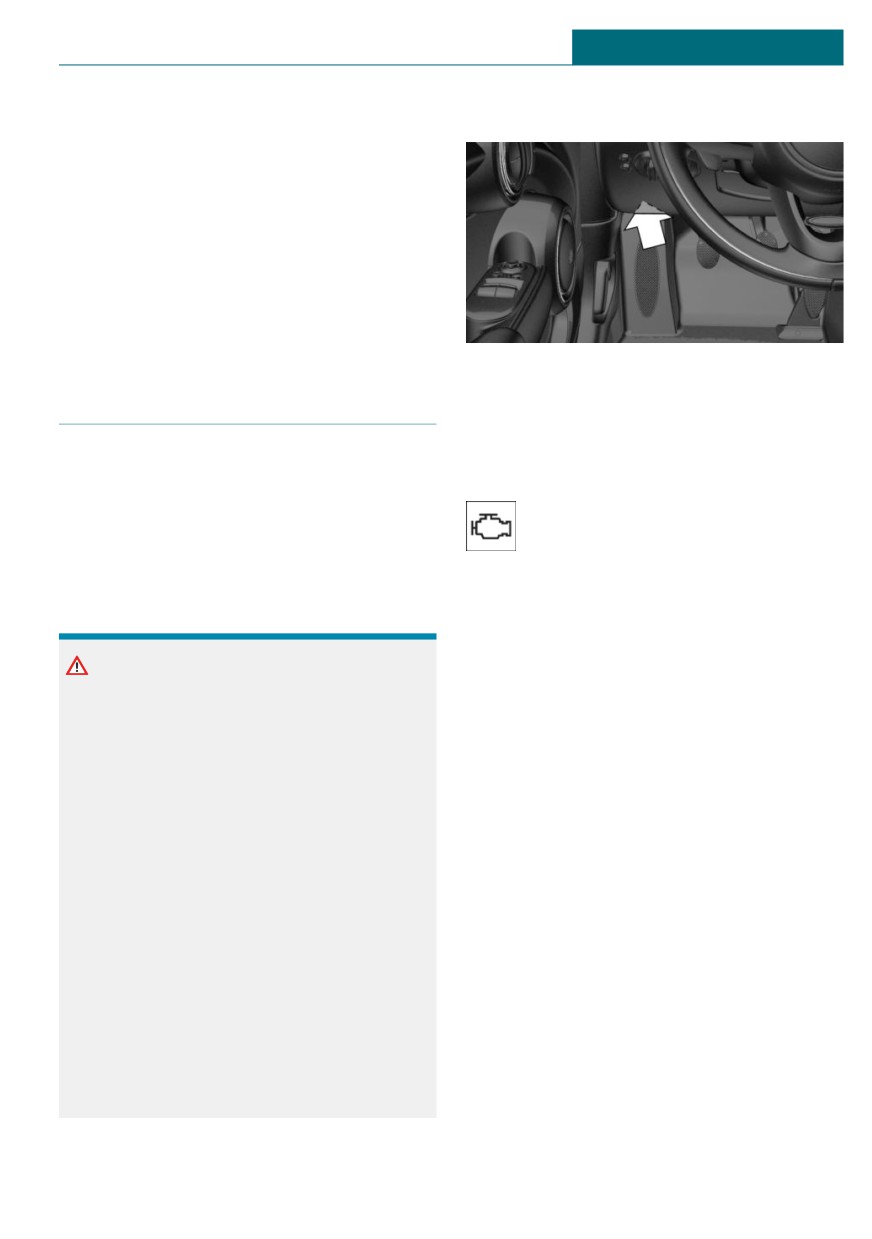
There is an OBD socket on the driver's side
Socket for OBD Onboard Diag-
for checking the primary components in the
nosis
vehicle's emissions.
General information
Emissions
Devices connected to the OBD socket trig-
- The warning light lights up:
ger the alarm system when the vehicle is
locked. Remove any devices connected at
Emissions are deteriorating.
the OBD socket before locking the vehicle.
Have the vehicle checked as soon
as possible.
Safety information
-
The warning light flashes under certain
circumstances:
This indicates that there is excessive
NOTICE
misfiring in the engine.
The socket for Onboard Diagnosis is an in-
Reduce the vehicle speed and have the
tricate component intended to be used in
system checked immediately; otherwise,
conjunction with specialized equipment to
serious engine misfiring within a brief
check the vehicle’s primary emissions sys-
period can seriously damage emission
tem. Improper use of the socket for On-
control components, in particular the
board Diagnosis, or contact with the
catalytic converter.
socket for Onboard Diagnosis for other
than its intended purpose, can cause vehi-
cle malfunctions and creates risks of per-
sonal and property damage. Given the fore-
going, the manufacture of your vehicle
strongly recommends that access to the
socket for Onboard Diagnosis be limited to
a dealer's service center or another quali-
fied service center or repair shop or other
persons that have the specialized training
and equipment for purposes of properly
utilizing the socket for Onboard Diagnosis.
271
MOBILITY
Replacing components
Replacing components
Vehicle features and options
Wiper blades
This chapter describes all standard, country-
Safety information
specific and optional features offered with
the series. It also describes features and
NOTICE
functions that are not necessarily available
in your vehicle, e.g., due to the selected op-
The window may sustain damage if the
tions or country versions. This also applies
wiper falls onto it without the wiper blade
to safety-related functions and systems.
installed. There is a risk of damage to
When using these functions and systems,
property. Hold the wiper firmly when
the applicable laws and regulations must be
changing the wiper blade. Do not fold or
observed.
switch on the wiper without a wiper blade
installed.
Vehicle tool kit
NOTICE
Folded-away wipers can be jammed when
the hood is opened. There is a risk of dam-
age to property. Make sure that the wipers
with the wiper blades mounted are folded
down onto the windshield before opening
the hood.
Replacing the front wiper blades
Depending on the vehicle equipment, the
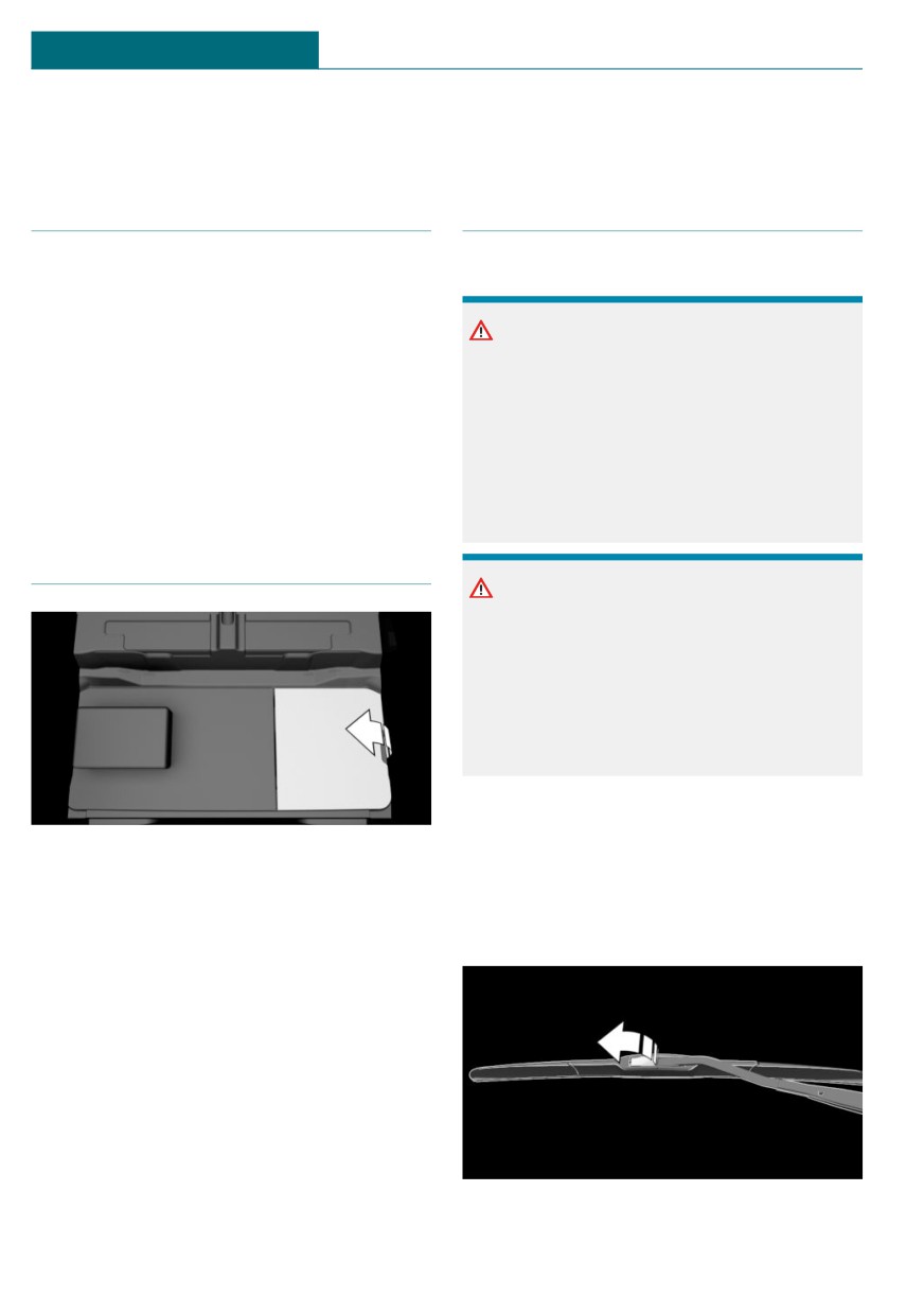
1. To change the wiper blades, fold up the
onboard vehicle tool kit is located on the
wiper arms.
right side under the cargo floor panel or in a
2. Fold up and hold the wiper arm firmly.
bag on the right side of the cargo area.
3. Open the wiper blade lock, arrow.
After use, secure the bag with the onboard
vehicle tool kit on a lashing eye again.
272
Replacing components
MOBILITY
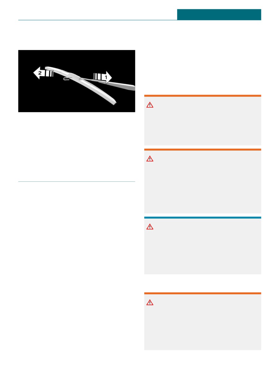
4. Pull the wiper blade down out of the
cially designated as Class 1 light-emitting
holder on the wiper arm, arrow 1.
diodes.
Follow the safety information, refer to
page 273.
Safety information
Lights and bulbs
Warning
Bulbs can get hot during operation. Con-
5. Pull the wiper blade free from the holder
tact with the bulbs can cause burns. There
of the wiper arm, arrow 2.
is a risk of injury. Only change bulbs after
6. Insert and latch a new wiper blade in re-
they have cooled off.
verse order.
7. Fold down the wiper arm.
Warning
Work on switched-on lighting systems can
Light and bulb replacement
cause short circuits. There is a risk of in-
jury or risk of damage to property. When
working on the lighting system, switch off
General information
the lights in question. If necessary, heed
the bulb manufacturer's instructions.
Lights and bulbs
Lights and bulbs make an essential contri-
bution to vehicle safety.
NOTICE
The manufacturer of the vehicle recom-
Dirty bulbs have a reduced service life.
mends that you have appropriate work per-
There is a risk of damage to property. Do
formed by a dealer’s service center or an-
not hold new bulbs with your bare hands.
other qualified service center or repair shop
Use a clean cloth or something similar, or
if you are unfamiliar with it or if it has not
hold the bulb by its base.
been described here.
A spare light box is available from a dealer's
service center or another qualified service
Light-emitting diodes (LEDs)
center or repair shop.
Follow the safety information, refer to
Warning
page 273.
Intensive brightness can irritate or dam-
age the retina of the eye. There is a risk of
Light-emitting diodes (LEDs)
injury. Do not look directly into the head-
Some items of equipment use light-emitting
lights or other light sources. Do not re-
diodes installed behind a cover as a light
move the LED covers.
source. These light-emitting diodes are re-
lated to conventional lasers and are offi-
273
MOBILITY
Replacing components
Headlight glass
55-watt bulb, HB2.
Condensation can form on the inside of the
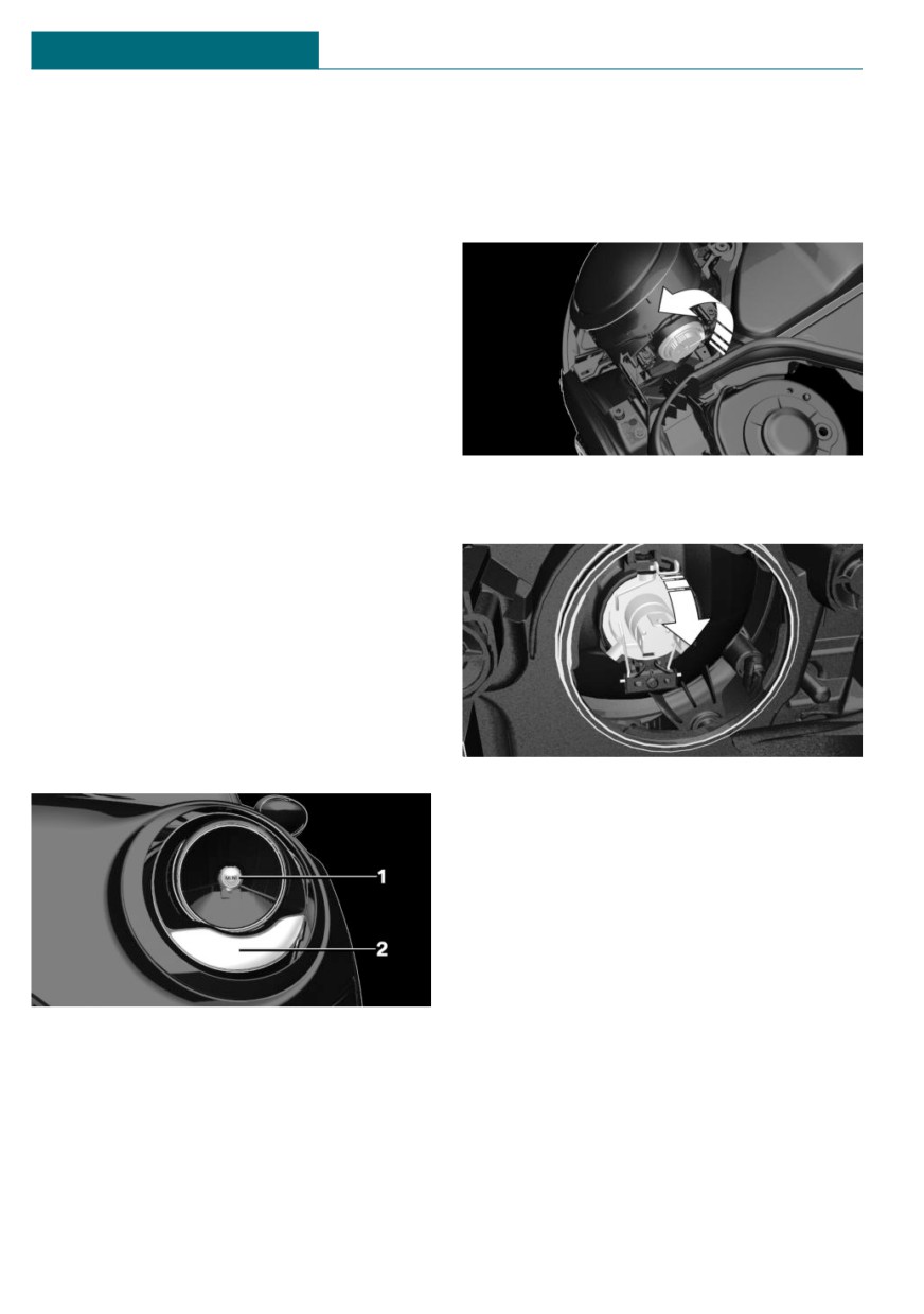
1.
Open the hood, refer to page 262.
headlight glass in cool or humid weather.
2.
Turn the lid counterclockwise, arrow,
When driving with the lights switched on,
and remove.
the condensation evaporates after a short
time. The headlight glass does not need to
be changed.
If despite driving with the headlights
switched on, increasing humidity forms, for
instance water droplets in the light, have
the headlights checked.
Headlight setting
The headlight adjustments can be affected
by changing lights and bulbs. After the
3.
Pull off the connector.
headlight adjustment was changed, have it
4.
Unclip spring clip, arrow, and fold down.
checked and, if necessary, corrected by a
dealer’s service center or another qualified
service center or repair shop.
Front halogen lights, bulb
replacement
Overview
Halogen headlights
5.
Remove the bulb from the headlight
housing.
6.
Insert the new bulb and install the cover
in the reverse order.
Turn signal
Follow the general instructions on lights
and bulbs, refer to page 273.
1
Low beams/high beams
2
Turn signal
Low beams/high beams
Follow the general instructions on lights
and bulbs, refer to page 273.
274
Replacing components
MOBILITY
21-watt bulb, PY21W.
In the case of a malfunction, contact a deal-
er's service center or another qualified serv-
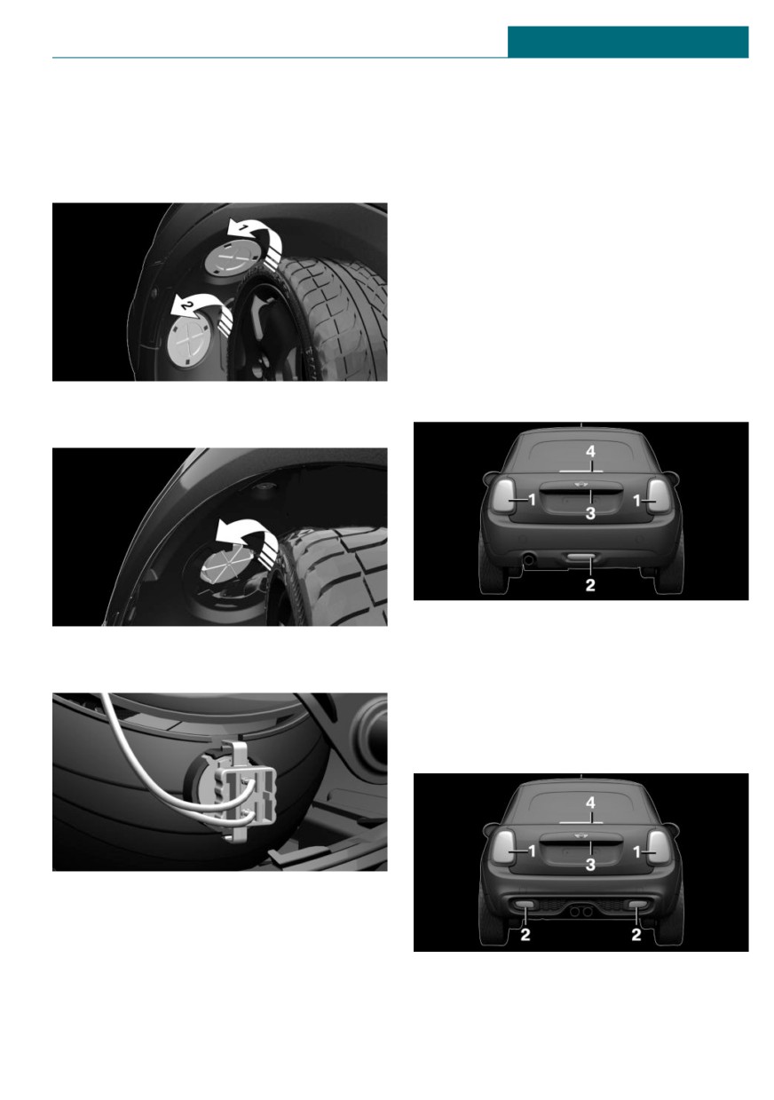
1. Turn the steering wheel.
ice center or repair shop.
2. Turn the lid counterclockwise, arrow 1,
and remove.
LED front fog lights
These front fog lights are made using LED
technology. In the case of a malfunction,
contact a dealer's service center or another
qualified service center or repair shop.
Tail lights, bulb replacement
Overview
Vehicles with a rear fog light
3. Unscrew the inner cover counterclock-
wise, and remove it.
1
Side tail lights
4. Turn the bulb socket counterclockwise
2
Rear fog light
and remove it from the bulb housing.
3
License plate light
4
Center brake light
Vehicle with two rear fog lights
5. Pull the bulb out of the fixture.
6. Insert the new bulb and install the cover
in the reverse order.
1
Side tail lights
LED front lights, bulb replacement
2
Rear fog lights
All lights feature LED technology.
275
MOBILITY
Replacing components
- Bulb, turn signals: P21W.
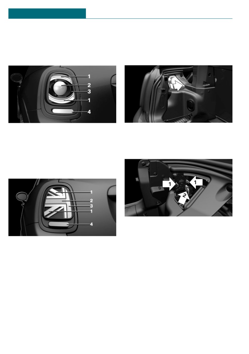
3
License plate light
- Bulb, reversing lights: P21W.
4
Center brake light
1. Opening trunk lid.
Side tail lights
2. Remove left or right cover.
1
Tail lights
3. Through the opening, loosen the plug
connector, arrow 2 on the bulb holder.
2
Turn signal
Press the latches together, arrows 1, and
3
Brake light
remove the bulb holder.
4
Reversing lights
Side tail lights with Union Jack
4. Remove the bulb holder from the open-
ing.
5. Press the nonworking bulb gently into
1
Tail lights
the socket, turn counterclockwise and
2
Turn signals/brake lights
remove.
3
Turn signals/brake lights
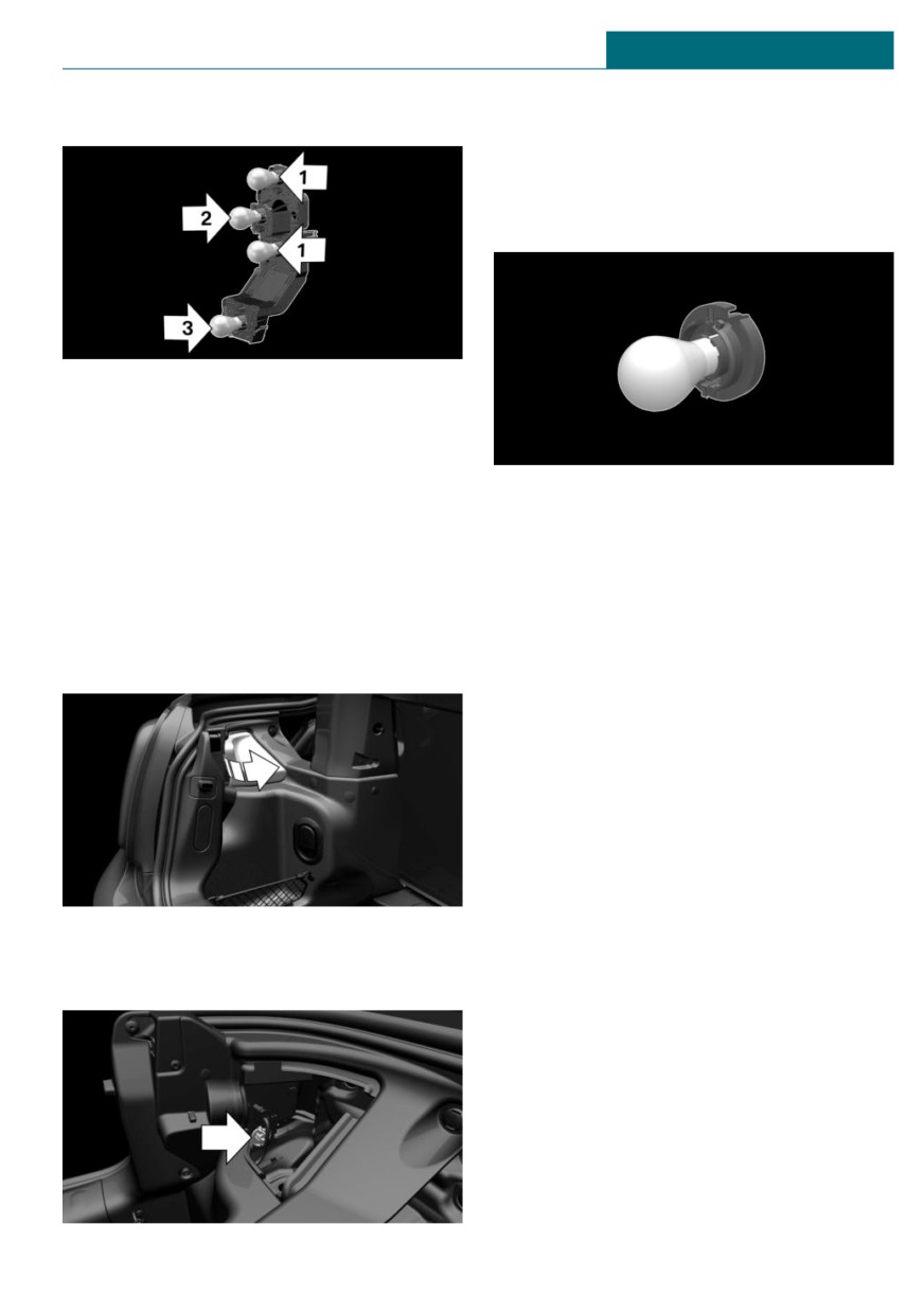
- Arrow 1: brake lights
4
Reversing lights
- Arrow 2: turn signal
Side tail lights
Without Union Jack
Follow the general instructions on lights
and bulbs, refer to page 273.
– Bulb, brake lights: H21W.
276
Replacing components
MOBILITY
– Arrow 3: reversing light
4. Remove the bulb holder from the open-
ing.
5. Press the nonworking bulb gently into
the socket, turn counterclockwise and
remove.
6. Proceed in the reverse order to insert
the new bulb and attach the bulb holder.
Make sure that the bulb holder engages
in all fasteners.
6. Proceed in the reverse order to insert
With Union Jack
the new bulb and attach the bulb holder.
Follow the general instructions on lights
Make sure that the bulb holder engages
and bulbs, refer to page 273.
in all fasteners.
Bulb, reversing lights: P21W.
Central brake light and license plate
1. Opening trunk lid.
lights
2. Remove left or right cover.
Follow the general instructions on lights
and bulbs, refer to page 273.
The lights feature LED technology. In the
case of a malfunction, contact a dealer's
service center or another qualified service
center or repair shop.
Side turn signal, bulb replacement
Follow the general instructions on lights
and bulbs, refer to page 273.
3. Turn the bulb holder for the reversing
Bulbs:
light, arrow, counterclockwise and re-
move it.
277