MINI Convertible (2021 year). Manual in english - page 7
CONTROLS
Interior equipment
cessful, the "C" is replaced by the points
Front passenger side dash-
of the compass.
board
Left/right-hand steering
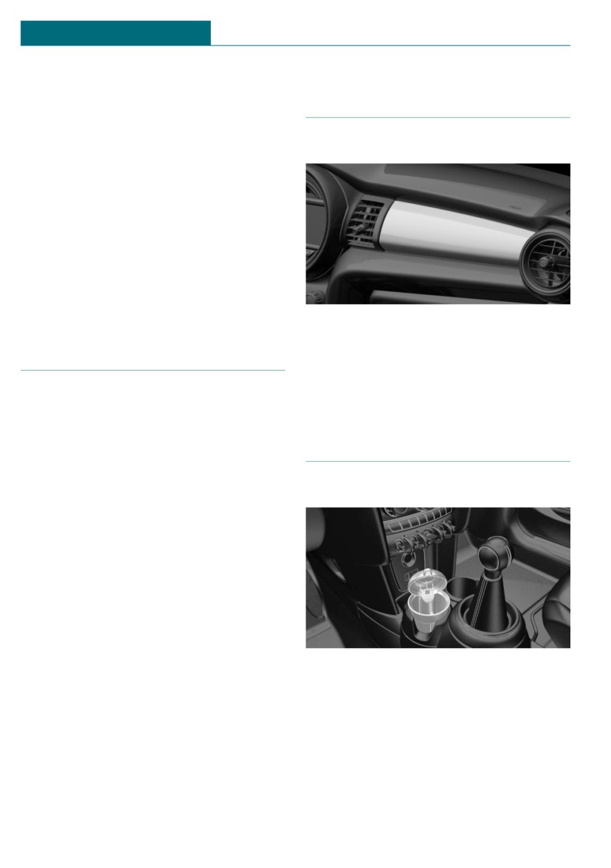
Decorative trim
The digital compass is already set for right
or left-hand steering at the factory.
Setting the language
Press and hold the control button for ap-
prox. 12 to 13 seconds. Briefly press the
control button again to switch between
English "E" and German "O".
Settings are stored automatically after ap-
proximately 10 seconds.
Customized decorative trim panels for the
dashboard on the front passenger side are
Sun visor
available as original MINI accessories de-
pending on the equipment specification.
Follow the assembly instructions.
Glare shield
To provide protection against glare, fold the
sun visor down or pivot it to the side.
Ashtray/cigarette lighter
Vanity mirror
A vanity mirror is located in the sun visor
Overview
behind a cover.
The ashtray is located in one of the frontal
cup holders, the cigarette lighter above it in
the center console.
Ashtray
In order to empty the ashtray, remove the
ashtray from the cup holder.
210
Interior equipment
CONTROLS
Cigarette lighter
Do not damage the socket by using non-
compatible connectors.
Safety information
Safety information
Warning
Warning
Contact with the hot heating element or
the hot socket of the cigarette lighter can
Devices and cables in the unfolding area of
cause burns. Flammable materials can ig-
the airbags, such as portable navigation
nite if the cigarette lighter falls down or is
devices, can hinder the unfolding of the
held against the objects. There is a risk of
airbag or be thrown around in the car's in-
fire and injuries. There is a risk of damage
terior during unfolding. There is a risk of
to property. Take hold of the cigarette
injury. Make sure that devices and cables
lighter by its handle. Make sure that chil-
are not in the airbag's area of unfolding.
dren do not use the cigarette lighter.
NOTICE
NOTICE
Battery chargers for the vehicle battery
If metal objects fall into the socket, they
can work with high voltages and currents,
can cause a short circuit. There is a risk of
which means that the 12 volt on-board
damage to property. Replace the cigarette
network can be overloaded or damaged.
lighter or socket cover again after using
There is a risk of damage to property. Only
the socket.
connect battery chargers for the vehicle
battery to the starting aid terminals in the
engine compartment.
Operation
Push in the cigarette lighter.
NOTICE
The cigarette lighter can be
removed as soon as it pops
If metal objects fall into the socket, they
back out.
can cause a short circuit. There is a risk of
damage to property. Replace the cigarette
lighter or socket cover again after using
the socket.
Sockets
Concept
The lighter socket can be used as a socket
for electrical equipment while the ignition
is switched on or the engine is running.
General information
The total load of all sockets must not exceed
140 watts at 12 volts.
211
CONTROLS
Interior equipment
In the center console
In the center console
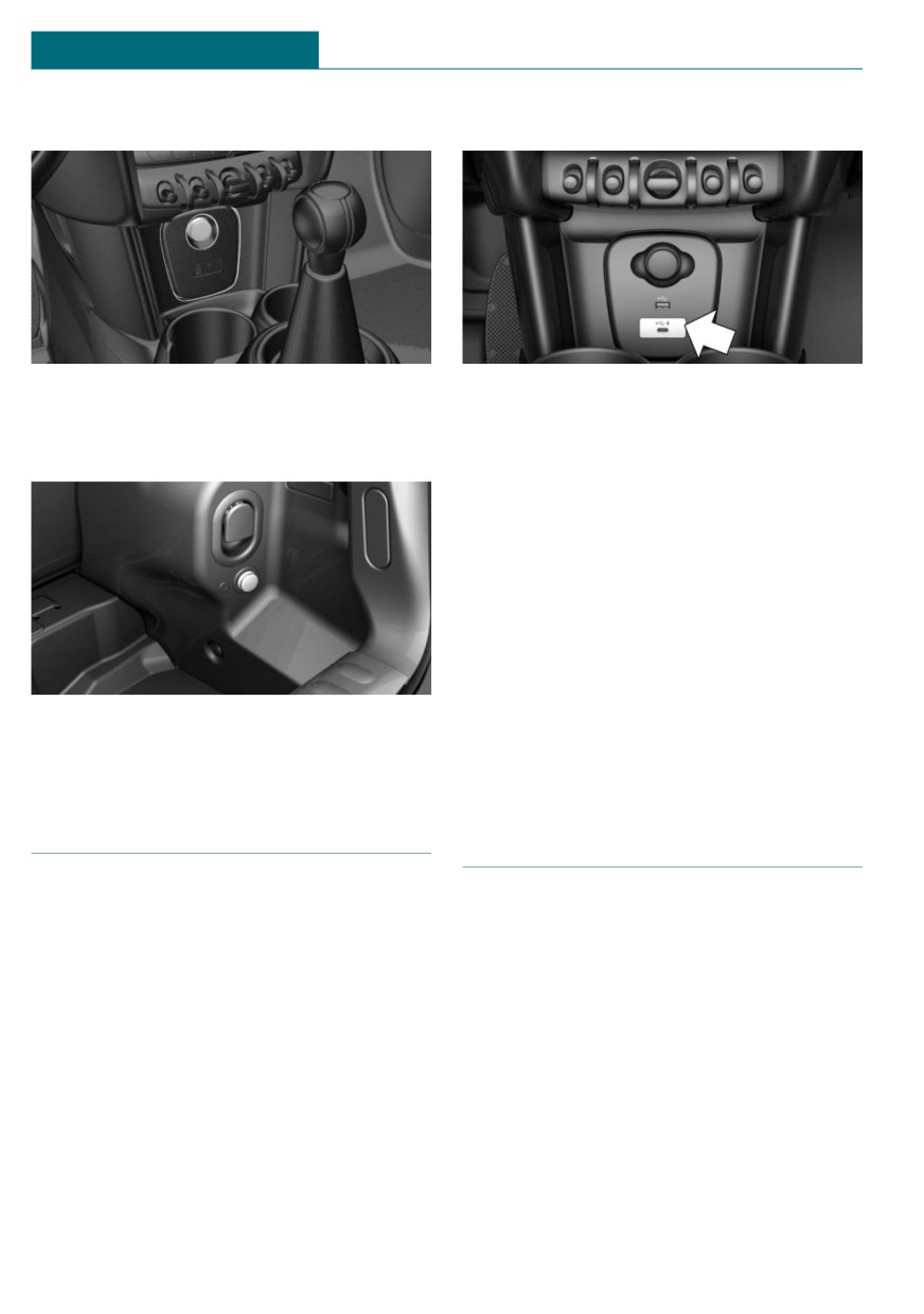
Remove the cover or cigarette lighter.
Depending on the equipment version, a USB
port Type A or a USB port Type A and a USB
port Type C are located in the front of the
In the cargo area
center console.
Properties of upper USB port:
- USB port Type A.
- For charging mobile devices and for
data transfer.
- Charge current: max. 1.5 A.
Properties of lower USB port:
- USB port Type C.
- For charging mobile devices and for
The socket is located on the right side in
data transfer.
the cargo area.
- Charge current: max. 3 A.
USB port
Wireless charging tray
General information
Concept
Follow the information regarding the con-
The wireless charging tray enables the fol-
nection of mobile devices to the USB port in
lowing functions to be performed without
the section on USB connections, refer to
cables:
page 53.
- Charging the rechargeable battery of a
mobile phone with Qi capability and of
other mobile devices, which support the
Qi standard.
- Connect the mobile phone to the exter-
nal antenna.
Depending on the country, this provides
for better network reception and a con-
sistent reproduction quality.
212
Interior equipment
CONTROLS
General information
the device and the tray may impair the
card function. There is a risk of injury and
When inserting the mobile phone, make
risk of damage to property. When charg-
sure there are no objects between it and the
ing mobile devices, make sure there are no
wireless charging tray.
objects between the device and the tray.
During charging, the surface of the tray and
the mobile phone may become warm.
Higher temperatures may lead to a reduc-
NOTICE
tion in the charge current through the mo-
bile phone, and in isolated cases the charg-
The tray is intended for mobile phones up
ing process is paused temporarily. Follow
to a particular size. Forceful inserting of
the relevant instructions in the mobile
the mobile phone into the tray can damage
phone owner's manual.
the tray or the mobile phone. There is a
risk of damage to property. Observe the
NOTE
maximum dimensions for mobile phones.
Do not force the mobile phone into the
This device has been tested for human ex-
tray.
posure limits and found compliant at a mini-
mum distance of 4 in/10 cm during opera-
tion.
Functional requirements
Therefore, a distance of 4 in/10 cm must be
- Ignition or standby state is switched on.
maintained in every direction when operat-
ing the device.
- The mobile phone must compatibly sup-
port the required Qi standard. Compati-
ble mobile phones, refer to page 51.
If the mobile phone does not support the
Qi standard, the mobile phone can be
charged using a special Qi-compatible
charging case.
- Use only protective jackets and covers
up to a maximum thickness of
0.07 in/2 mm. Otherwise, the charging
function may be impaired.
Mounting position of the product.
- The mobile phone must not exceed the
maximum size of approximately 5.9 x
Safety information
3.07 x 0.62 in/150 x 78 x 16 mm.
Overview
Warning
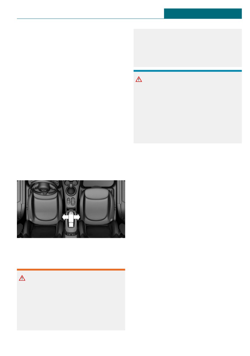
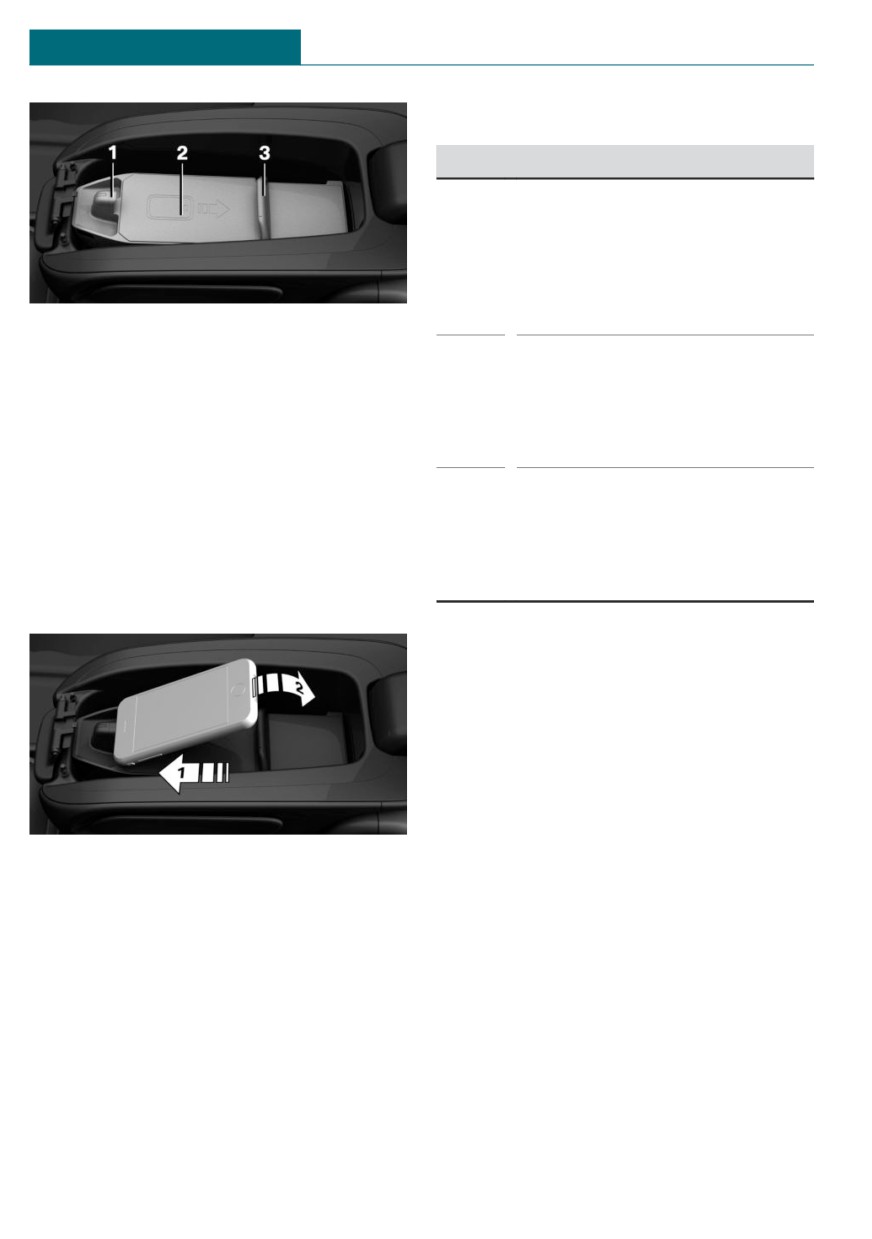
The wireless charging tray is located in the
When charging a device that meets the Qi
center armrest.
standard in the wireless charging tray, any
metal objects located between the device
and the tray can become very hot. Placing
storage devices or electronic cards, such
as chip cards, cards with magnetic strips
or cards for signal transmission, between
213
CONTROLS
Interior equipment
LED displays
Color
Meaning
Blue
The mobile phone is charging.
Depending on the model, the
blue LED is no longer illuminated
once the inserted mobile phone
with Qi capability is fully
charged.
1
Front holder with LED
2
Storage area
Or-
The mobile phone is not charg-
ange
ing.
3
Movable clamp
Temperature on the mobile
phone possibly too high or for-
Inserting the mobile phone
eign object in the charging tray.
1.
Open center armrest, refer to vehicle
Red
The mobile phone is not charg-
ing.
2.
Push back the clamp.
Contact a dealer’s service center
3.
Insert the mobile phone with the display
or another qualified service cen-
facing upward in the direction of the
ter or repair shop.
front holder, arrow 1.
System limits
At high temperatures on the mobile phone
or in the vehicle, the charging functions of
the mobile phone may be limited and some
functions may no longer work.
LTE-Compensator - Information
and User Manual
Your car is equipped with a wireless charg-
4.
Place the mobile phone in the storage
ing tray (WCA) to charge your mobile phone
area, arrow 2.
and connect it to the mobile network. To en-
5.
Push the clamp forward and clamp the
sure the best possible connection a signal
mobile phone in the tray.
booster (LTE-Compensator) is used in con-
junction with the WCA. The following para-
6.
Close the center armrest.
graphs refer to this booster:
This is a CONSUMER device.
Removing the mobile phone
BEFORE USE, you MUST REGISTER THIS
1. Open the center armrest.
DEVICE with your wireless provider and
2. Push the clamp back and remove the
have your provider's consent. Most wireless
mobile phone.
providers consent to the use of Compensa-
tors. Some providers may not consent to the
use of this device on their network. If you
214
Interior equipment
CONTROLS
are unsure, contact your provider. You
tennas or coupling devices will cause the
MUST operate this device with approved an-
cease of the booster´s operating license.
tennas and cables as specified by the manu-
The booster device fulfills the network pro-
facturer. Antennas MUST be installed at
tection standards as required by the FCC,
least 20 cm (8 inches) from any person. You
such as intermodulation limits, oscillation
MUST cease operating this device immedi-
detection and gain limits.
ately if requested by the FCC or a licensed
Booster Manufacturer: Kathrein Automotive
wireless service provider. Warning E911 lo-
cation information may not be provided or
Model Number: LTECOMPB0
may be inaccurate for calls served by using
Part Number: 6803145-01
this device.
FCC-ID: 2ACC7LTECOMPB0
Please observe additionally the following in-
formation
- Sprint Nextel will allow consumers to
register their signal boosters by calling
their toll-free number.
- T-Mobile online registration link:
SignalBooster#).
- Verizon’s online registration link:
wcms/consumer/register-signal-boos-
ter.html).
- AT&T online registration link (https://
securec45.securewebsession.com/
attsignalbooster.com/).
- U.S.Cellular online registration link
support/fcc-booster-registration.jsp).
Before use you must register your booster
device with your wireless provider.
If you should be requested by the FCC to
cease operating your booster, you are not
allowed to insert your mobile phone in the
charging tray anymore unless the booster is
permanently deactivated by your local MINI
dealer.
You must not remove the booster from the
car nor use it with any other than the prein-
stalled coupling device or antenna. Any
modification of the existing antenna or cou-
pling device as well as the use of other an-
215

CONTROLS
Storage compartments
Storage compartments
- Glove compartment on the front passen-
Vehicle features and options
ger side.
- Compartments in the doors.
This chapter describes all standard, country-
specific and optional features offered with
- Storage compartment in the center arm-
the series. It also describes features and
rest.
functions that are not necessarily available
- Storage compartment in front of the cup
in your vehicle, e.g., due to the selected op-
holders.
tions or country versions. This also applies
- Storage compartments in the cargo area.
to safety-related functions and systems.
- Storage tray in the center console.
When using these functions and systems,
the applicable laws and regulations must be
- Pockets on the backrests of the front
observed.
seats.
Safety information
Glove compartment
Safety information
Warning
Loose objects or devices with a cable con-
Warning
nection to the vehicle, for instance mobile
Folded open, the glove compartment pro-
phones, can be thrown about the car's in-
trudes in the car's interior. Objects in the
terior while driving, for instance in the
glove compartment can be thrown into the
event of an accident, braking or evasive
car's interior while driving, for instance in
maneuver. There is a risk of injury. Secure
the event of an accident, braking or eva-
loose objects or devices with a cable con-
sive maneuvers. There is a risk of injury.
nection to the vehicle in the car's interior.
Always close the glove compartment im-
mediately after using it.
NOTICE
Anti-slip pads such as anti-slip mats can
damage the dashboard. There is a risk of
damage to property. Do not use anti-slip
pads.
Overview
The following storage compartments are
available in the car's interior:
216
Storage compartments
CONTROLS
Opening
interior. There is a risk of injury or risk of
damage to property. Do not use any break-
able objects while driving. Only stow
breakable objects in closed storage com-
partments.
Center armrest
General information
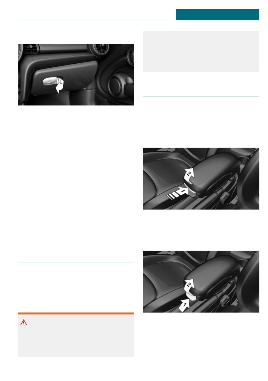
Pull the handle.
The center armrest contains a storage com-
The light in the glove compartment
partment.
switches on.
Opening
Closing
Fold up the cover.
Locking
The glove compartment can be locked with
an integrated key to separately secure the
trunk lid, for instance.
This prevents access to the glove compart-
ment and to the cargo area.
Press button, arrow 1, and open center arm-
After the glove compartment is locked, the
rest upward, arrow 2.
vehicle key can be handed over, such as at a
hotel, without the integrated key.
Adjusting the height
Compartments in the doors
General information
There are storage compartments in the
doors.
Safety information
Press button, arrow 1, and swing center
Warning
armrest upward or downward into the de-
Breakable objects, such as glass bottles or
sired height, arrow 2.
glasses, can break in the event of an acci-
dent or a braking or evasive maneuver.
Broken glass can be scattered in the car's
217
CONTROLS
Storage compartments
Cup holders
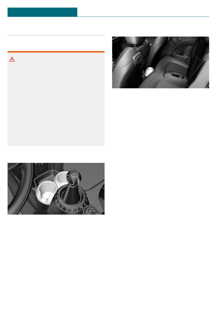
Rear
Safety information
Warning
Unsuitable containers in the cup holders
may damage the cup holders or be thrown
about the car’s interior in the event of an
accident, an evasive maneuver, or forceful
braking. Spilled liquids can distract from
In front of the rear seats.
the traffic conditions and lead to an acci-
dent. Hot drinks can damage the cup
holder or lead to scalding. There is a risk
of injury or risk of damage to property. Do
not force objects into the cup holder. Use
lightweight, shatterproof, and sealable
containers. Do not transport hot bever-
ages.
Front
In the center console.
218

Cargo area
CONTROLS
Cargo area
loose objects or devices with a cable con-
Vehicle features and options
nection to the vehicle in the car's interior.
This chapter describes all standard, country-
specific and optional features offered with
Warning
the series. It also describes features and
functions that are not necessarily available
Improperly stowed objects can shift and
in your vehicle, e.g., due to the selected op-
be thrown into the car's interior, for in-
tions or country versions. This also applies
stance in the event of an accident or dur-
to safety-related functions and systems.
ing braking and evasive maneuver. Vehi-
When using these functions and systems,
cle occupants can be hit and injured. There
the applicable laws and regulations must be
is a risk of injury. Stow and secure objects
observed.
and cargo properly.
Loading
NOTICE
Fluids in the cargo area can cause damage.
Safety information
There is a risk of damage to property.
Make sure that no fluids leak in the cargo
area.
Warning
High gross weight can overheat the tires,
damage them internally and cause a sud-
Steps for Determining Correct Load
den drop in tire inflation pressure. Driving
Limit
characteristics may be negatively im-
1. Locate the statement “The combined
pacted, reducing lane stability, lengthen-
weight of occupants and cargo should
ing the braking distances and changing
never exceed XXX kg or XXX lbs” on
the steering response. There is a risk of
your vehicle’s placard.
accident. Pay attention to the permitted
load capacity of the tires and never exceed
2. Determine the combined weight of the
the permitted gross weight.
driver and passengers that will be riding
in your vehicle.
3. Subtract the combined weight of the
Warning
driver and passengers from XXX kg or
XXX lbs
Loose objects or devices with a cable con-
nection to the vehicle, for instance mobile
4. The resulting figure equals the available
phones, can be thrown about the car's in-
amount of cargo and luggage load ca-
terior while driving, for instance in the
pacity. For example, if the “XXX”
event of an accident, braking or evasive
amount equals 1,400 lbs and there will
maneuver. There is a risk of injury. Secure
be five 150 lbs passengers in your vehi-
cle, the amount of available cargo and
219
CONTROLS
Cargo area
luggage load capacity is 650 lbs (1,400 -
- Do not stack cargo above the top edge of
750 (5 x 150) = 650 lbs)
the backrests.
5. Determine the combined weight of lug-
- Small and light cargo: secure with
gage and cargo being loaded on the ve-
ratchet straps or draw straps.
hicle. That weight may not safely exceed
- Larger and heavy cargo: secure with
the available cargo and luggage load ca-
cargo straps.
pacity calculated in Step 4.
6. If your vehicle will be towing a trailer,
load from your trailer will be transferred
Loading aid
to your vehicle. Consult this manual to
determine how this reduces the availa-
Concept
ble cargo and luggage load capacity of
your vehicle.
For easier loading, the vehicle is equipped
with loading aid. When the loading aid is
opened, objects can be stowed that would
Load
not otherwise fit through the trunk lid
opening.
Safety information
Warning
When opening and closing the loading aid,
body parts can be jammed, for instance by
the mechanism. There is a risk of injury.
Make sure that the area of movement of
the loading aid is clear during operation.
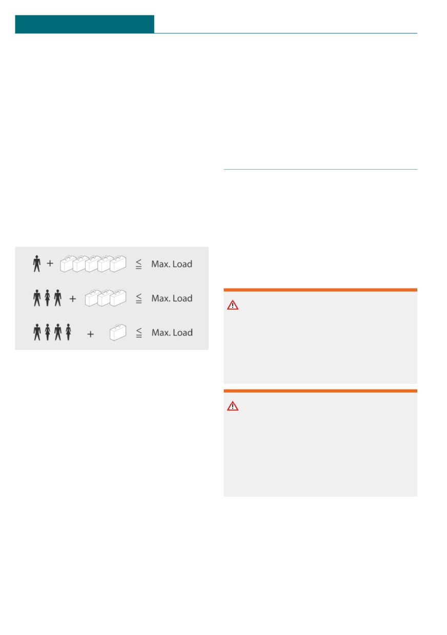
The maximum load is the sum of the weight
of the occupants and the cargo.
The greater the weight of the occupants,
Warning
the less cargo that can be transported.
With a lifted loading aid, vehicle parts can
Stowing and securing cargo
protrude and limit the view. There is a
danger of accidents and property damage.
- Cover sharp edges and corners on the
Before driving off, make sure that the load-
cargo.
ing aid is completely lowered and the
- Heavy cargo: stow as far forward as pos-
trunk lid is closed.
sible, directly behind and at the bottom
of the rear passenger seat backrests.
- Very heavy cargo: when the rear seat is
not occupied, secure each of the outer
safety belts in the opposite buckle.
- If necessary, fold down the rear back-
rests to stow large cargo.
220
Cargo area
CONTROLS
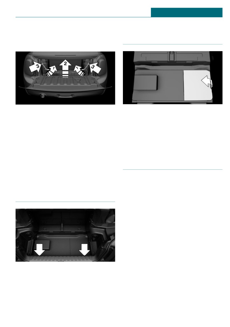
Opening the loading aid
Storage space under cargo
1. Unlock the convertible top using the
floor panel
handles, arrows 1.
2. Lift convertible top, arrow 2.
Located under the cargo floor panel on the
right side is a trough for the onboard vehi-
3. Fold back the handles and place on the
cle tool kit.
brackets, arrows 3.
Fold the right side of the cargo floor panel
upward to remove the onboard vehicle tool
Closing the loading aid
kit.
1. Remove handles from the brackets.
2. Push convertible top down and hold.
3. Push the handles outward to lock the
Enlarging the cargo area
convertible top.
4. Check that the convertible top is locked.
Concept
The cargo area can be enlarged as follows:
- The rear seat backrests can be folded
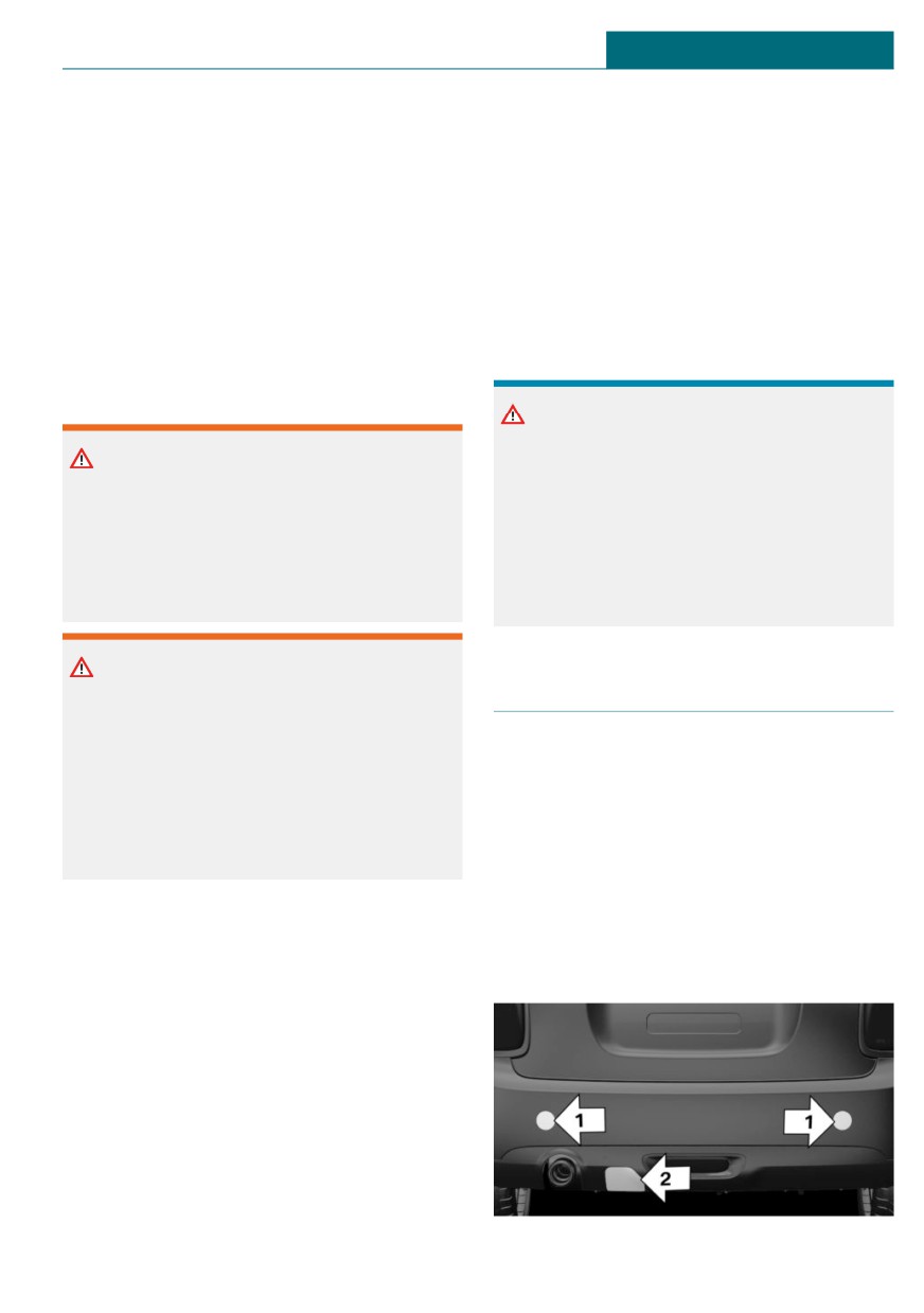
Lashing eyes in the cargo area
down.
- The cargo area partition can be swung
upward when the convertible top is
closed.
General information
The rear seat backrest is divided into two
parts at a ratio of 50 to 50.
The rear seat backrests can be folded down
from the cargo area.
To secure the cargo there are two lashing
eyes in the cargo area.
Attach load securing aids, such as lashing
straps, tensioning straps, draw straps or
cargo nets, to the lashing eyes in the cargo
area.
221

CONTROLS
Cargo area
Safety information
Folding down the rear seat
backrest from the cargo area
Warning
1. Before the backrest is folded down, re-
move the respective safety belt from the
Danger of jamming with folding down the
rear belt guide, refer to page 86.
backrests. There is a risk of injury or risk
of damage to property. Make sure that the
2. Pull the lever.
area of movement of the rear backrest and
the of the head restraint is clear prior to
folding down.
Warning
If a rear seat backrest is not locked, unse-
cured cargo can be thrown about the car’s
interior; for instance, in the event of an ac-
cident, braking or an evasive maneuver.
3. Fold the rear seat backrest forward.
There is a risk of injury. Make sure that
the rear seat backrest is locked after fold-
Folding back the backrest
ing it back.
1. Fold up the backrest and press it into
the latch. Make sure that the safety belt
is not caught behind the backrest or in
Warning
between the backrest and the rear seats.
The stability of the child restraint system
2. Close the belt guide loop of the rear belt
is limited or compromised with incorrect
guide, refer to page 86.
seat adjustment or improper installation of
the child seat. There is a risk of injuries or
danger to life. Make sure that the child re-
Cargo area partition
straint system fits securely against the
1. Fold the convertible top upward as de-
backrest. If possible, adjust the backrest
scribed under Loading aid, refer to
tilt for all affected backrests and correctly
page 221.
adjust the seats. Make sure that seats and
2. Swing the cargo area partition upward
backrests are securely engaged or locked.
and pull backward out of the lower sup-
If possible, adjust the height of the head
ports, arrows 1.
restraints or remove them.
Warning
Body parts can be jammed when moving
the head restraint. There is a risk of injury.
Make sure that the area of movement is
clear when moving the head restraint.
222
Cargo area
CONTROLS
3. Insert the cargo area partition into the
upper supports, arrows 2, until it en-
gages and place down horizontally.
The loading aid cannot be locked if the
cargo area partition is not fully inserted
into the upper supports.
4. Fold the convertible top downward as
described under Loading aid, refer to
page 221, and lock it.
Return the cargo area partition into the
lower position so that the convertible top
can be used.
223
DRIVING TIPS
Things to remember when driving
Things to remember when driving
Vehicle features and options
Engine, transmission, and axle
drive
This chapter describes all standard, country-
specific and optional features offered with
Up to 1,200 miles/2,000 km
the series. It also describes features and
Do not exceed the maximum engine and
functions that are not necessarily available
road speed:
in your vehicle, e.g., due to the selected op-
- For gasoline engine 4,500 rpm and
tions or country versions. This also applies
100 mph/160 km/h.
to safety-related functions and systems.
Avoid full load or kickdown under all cir-
When using these functions and systems,
cumstances.
the applicable laws and regulations must be
observed.
From 1,200 miles/2,000 km
The engine and vehicle speed can gradually
Breaking-in period
be increased.
Tires
General information
Tire traction is not optimal due to manufac-
Moving parts need to begin working to-
turing circumstances when tires are brand-
gether smoothly.
new; they achieve their full traction poten-
The following instructions will help you to
tial after a break-in time.
achieve a long vehicle life and good effi-
Drive conservatively for the first
ciency.
200 miles/300 km.
During break-in, do not use the Launch
Control, refer to page 118.
Brake system
Brake discs and brake pads only reach their
Safety information
full effectiveness after ap-
prox. 300 miles/500 km. Drive moderately
Warning
during this break-in period.
Due to new parts and components, safety
and driver assistance systems can react
Clutch
with a delay. There is a risk of accident.
The function of the clutch reaches its opti-
After installing new parts or with a new
mal level only after a distance driven of ap-
vehicle, drive conservatively and inter-
prox. 300 miles/500 km. During this break-
vene early if necessary. Observe the break-
in period, engage the clutch gently.
in procedures of the respective parts and
components.
Following part replacement
The same break-in procedures should be ob-
served if any of the components mentioned
224

Things to remember when driving
DRIVING TIPS
above have to be renewed in the course of
the window. Do not open the door with
the vehicle's operating life.
force.
General driving notes
Hot exhaust gas system
Closing the trunk lid
Warning
High temperatures can occur underneath
Safety information
the body, for instance caused by the ex-
haust gas system, while driving. Contact
with the exhaust gas system can cause
Warning
burns. There is a risk of injury. Do not
An open trunk lid protrudes from the vehi-
touch the hot exhaust gas system, includ-
cle and can endanger occupants and other
ing the exhaust pipe.
traffic participants or damage the vehicle
in the event of an accident, braking or eva-
sive maneuvers. In addition, exhaust
Warning
fumes may enter the car's interior. There
is a risk of injury or risk of damage to
If combustible materials, such as leaves or
property. Do not drive with the trunk lid
grass, come in contact with hot parts of
open.
the exhaust gas system, these materials
can ignite. There is a risk of fire and inju-
ries. Do not remove the heat shields instal-
Driving with the trunk lid open
led and never apply undercoating to them.
Make sure that no combustible materials
If driving with the tailgate open cannot be
can come in contact with hot vehicle parts
avoided:
in driving operation, idle or during park-
- If the convertible top is closed, close all
ing.
windows and the sliding sun roof.
- Greatly increase the air flow from the
vents.
Mobile communication devices in
- Drive moderately.
the vehicle
Ice on window glass
Warning
Vehicle electronics and mobile phones can
NOTICE
influence one another. There is radiation
due to the transmission operations of mo-
The window will be lowered slightly when
bile phones. There is a risk of injury or
pulling on the door handle. In the event of
risk of damage to property. If possible, in
frost, the window may freeze up and not
the car's interior use only mobile phones
be lowered. There is a risk of damage to
with direct connections to an exterior an-
property. When pulling on the door han-
tenna in order to exclude mutual interfer-
dle, make sure that the window is lowered.
ence and deflect the radiation from the
If necessary, remove snow and ice from
car's interior.
225

DRIVING TIPS
Things to remember when driving
Hydroplaning
Perform an emergency stop in situations
that require such.
On wet or slushy roads, a wedge of water
can form between the tires and road sur-
Steering is still responsive. You can still
face.
avoid any obstacles with a minimum of
steering effort.
This phenomenon is referred to as hydro-
planing. It is characterized by a partial or
Pulsation of the brake pedal and sounds
complete loss of contact between the tires
from the hydraulic circuits indicate that
and the road surface, ultimately undermin-
ABS is in its active mode.
ing your ability to steer and brake the vehi-
cle.
Objects in the area around the pedals
Driving through water
Warning
Objects in the driver's floor area can limit
General information
the pedal distance or block a depressed
When driving through water, follow the fol-
pedal. There is a risk of accident. Stow ob-
lowing:
jects in the vehicle such that they are se-
- Deactivate Auto Start/Stop function.
cured and cannot enter into the driver's
floor area. Use floor mats that are suitable
- Drive through calm water only.
for the vehicle and can be safely attached
- Drive through water only if it is not
to the floor. Do not use loose floor mats
deeper than maximum 9.8 inches/25 cm.
and do not layer several floor mats. Make
- Drive through water no faster than
sure that there is sufficient clearance for
walking speed, up to 3 mph/5 km/h.
the pedals. Ensure that the floor mats are
securely fastened again after they were re-
Safety information
moved, for instance for cleaning.
NOTICE
Driving in wet conditions
When driving too quickly through too
When roads are wet, salted, or in heavy
deep water, water can enter into the en-
rain, gently press the brake pedal every few
gine compartment, the electrical system or
miles.
the transmission. There is a risk of damage
Ensure that this action does not endanger
to property. When driving through water,
other traffic.
do not exceed the maximum indicated wa-
ter level and the maximum speed for driv-
The heat generated during braking dries
ing through water.
brake discs and brake pads and protects
them against corrosion.
In this way braking efficiency will be avail-
Braking safely
able when you need it.
General information
The vehicle is equipped with an Antilock
Braking System ABS as a standard feature.
226
Things to remember when driving
DRIVING TIPS
Hills
their response - generally this cannot be
corrected.
General information
Drive long or steep downhill gradients in
Condensation water under the
the gear that requires least braking effort.
parked vehicle
Otherwise, the brakes may overheat and re-
When using the automatic climate control,
duce brake efficiency.
condensation water develops and collects
You can increase the engine's braking effect
underneath the vehicle.
by shifting down, going all the way to first
gear, if needed.
Ground clearance
Safety information
NOTICE
If the ground clearance is insufficient, e.g.,
Warning
curbs or underground garage entrances,
Light but consistent brake pressure can
contact with vehicle parts, e.g., spoiler,
lead to high temperatures, brakes wearing
and the underbody may occur. There is a
out and possibly even brake failure. There
risk of damage to property. Ensure that
is a risk of accident. Avoid placing exces-
there is sufficient ground clearance availa-
sive stress on the brake system.
ble.
Warning
Rear luggage rack
In idle state or with the engine switched
off, safety functions, for instance engine
braking effect, braking assistance and
General information
steering assistance, may not be available.
Installation only possible with rear luggage
There is a risk of accident. Do not attempt
rack preparation.
to drive in idle state or with the engine
Rear luggage racks that are classified by the
switched off.
manufacturer of the vehicle to be suitable
are available as special accessories.
Brake disc corrosion
Mounting
Corrosion on the brake discs and contami-
nation on the brake pads are increased by
COOPER
the following circumstances:
- Low mileage.
- Extended periods when the vehicle is
not used at all.
- Infrequent use of the brakes.
- Aggressive, acidic, or alkaline cleaning
agents.
Corrosion buildup on the brake discs will
cause a pulsating effect on the brakes in
227
DRIVING TIPS
Things to remember when driving
COOPER S
Keep activation times of power consumers
short with the engine switched off to pro-
tect the vehicle battery.
Driving on racetracks
Warning
The vehicle is not designed for use in M
Sport or motor sport type competition.
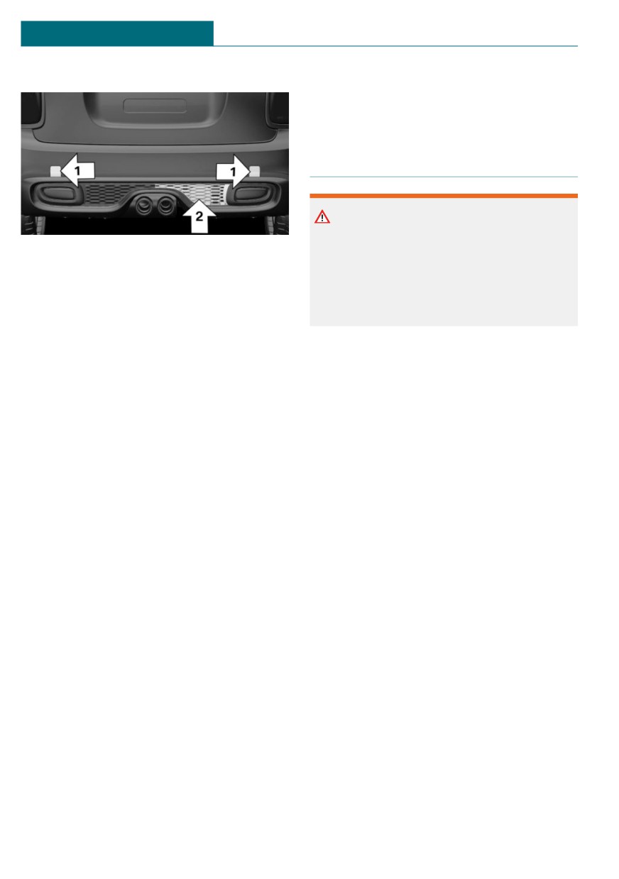
The fixing points, arrows 1, and the socket,
There is a risk of accident. Do not use the
arrow 2, are located below the covers in the
vehicle for M Sport or motor sport type
bumper.
competitions.
Remove the covers before installing the
rear luggage rack.
Higher mechanical and thermal loads during
racetrack operation lead to increased wear.
Loading
This wear is not covered by the warranty.
Because rear luggage racks raise the vehi-
cle's center of gravity when loaded, they
have a major effect on vehicle handling and
steering response.
Therefore, note the following when loading
and driving:
- Do not exceed the approved axle load
and the approved gross vehicle weight.
- Drive smoothly. Avoid sudden accelera-
tion and braking maneuvers. Take cor-
ners gently.
Power consumption
Before starting to drive, check the function
of the rear luggage rack lights. Before start-
ing to drive, check the function of the
trailer tail lights.
The rear luggage rack lights must not con-
sume more than:
- Turn signals: 42 watts per side.
- Rear lights: 50 watts per side.
- Brake lights: 84 watts in total.
- Rear fog lights: 42 watts in total.
- Backup light: 42 watts in total.
228

Reducing fuel consumption
DRIVING TIPS
Reducing fuel consumption
Attached parts on the vehicle impair the
Vehicle features and options
aerodynamics and increase the fuel con-
sumption.
This chapter describes all standard, country-
specific and optional features offered with
the series. It also describes features and
Close the windows
functions that are not necessarily available
in your vehicle, e.g., due to the selected op-
tions or country versions. This also applies
Open windows increase air resistance and
to safety-related functions and systems.
therefore lead to greater fuel consumption.
When using these functions and systems,
the applicable laws and regulations must be
observed.
Tires
General information
General information
Tires can affect consumption in various
ways, for instance tire size may influence
The vehicle contains advanced technologies
consumption.
for the reduction of consumption and emis-
sion values.
Check the tire inflation pressure
Fuel consumption depends on a number of
regularly
different factors.
Check and, if needed, correct the tire infla-
The implementation of certain measures,
tion pressure at least twice a month and be-
driving style and regular maintenance can
fore starting on a long trip.
influence fuel consumption and environ-
Low tire inflation pressure increases rolling
mental impact.
resistance and thus raises fuel consumption
and tire wear.
Remove unnecessary cargo
Drive away without delay
Additional weight increases fuel consump-
tion.
Do not wait for the engine to warm-up
while the vehicle remains stationary. Start
driving right away, but at moderate engine
Remove attached parts follow-
speeds.
ing use
This is the fastest way for the cold engine
to reach its operating temperature.
Remove rear luggage racks which are no
longer required following use.
229

DRIVING TIPS
Reducing fuel consumption
If the engine is switched off and then re-
Look well ahead when driving
started rather than leaving the engine run-
ning constantly, fuel consumption and emis-
Driving smoothly and proactively reduces
sions are reduced. Savings can begin within
fuel consumption.
a few seconds of switching off the engine.
Avoid unnecessary acceleration and brak-
In addition, fuel consumption is also deter-
ing.
mined by other factors, such as driving
By maintaining a suitable distance to the
style, road conditions, maintenance or envi-
vehicle driving ahead of you.
ronmental factors.
Avoid high engine speeds
Switch off any functions that
are not currently needed
Driving at low engine speeds lowers fuel
consumption and reduces wear.
Functions such as seat heating and the rear
If necessary, observe the vehicle's gear shift
window defroster require a lot of energy
indicator, refer to page 130.
and consume additional fuel, especially in
city and stop-and-go traffic.
Switch off these functions if they are not
Use coasting conditions
needed.
When approaching a red light, take your
foot off the accelerator and let the vehicle
Have maintenance carried out
coast to a halt.
For going downhill take your foot off the ac-
Have the vehicle maintained regularly to
celerator and let the vehicle roll.
achieve optimal vehicle efficiency and serv-
The flow of fuel is interrupted while coast-
ice life. MINI recommends that mainte-
ing.
nance work be performed by a MINI service
center.
Also note the MINI maintenance systems,
Switch off the engine during
refer to page 270.
longer stops
GREEN Mode
Switching off the engine
Switch off the engine during longer stops,
Concept
for instance at traffic lights, railroad cross-
ings or in traffic congestion.
GREEN Mode supports a driving style that
saves on consumption. For this purpose, the
engine control and comfort features, for in-
Auto Start/Stop function
stance the climate control output, are ad-
The Auto Start/Stop function of the vehicle
justed.
automatically switches off the engine dur-
For Steptronic transmission:
ing a stop.
230

Reducing fuel consumption
DRIVING TIPS
Under certain conditions the engine is auto-
Via the Central Information Display
matically decoupled from the transmission
(CID)
in the D selector lever position. The vehicle
1.
"My MINI"
continues traveling with the engine idling
to reduce consumption. The D selector lever
2. "Vehicle settings"
position remains engaged.
3. "Configure GREEN"
In addition, context-sensitive instructions
4. Select the desired setting.
are displayed to assist with an efficient
driving style.
Activating/deactivating the functions
The achieved extended range is displayed in
The following functions can be activated/
the instrument cluster as bonus range.
deactivated:
- "GREEN speed warning"
General information
- "GREEN climate control"
The system includes the following MINI-
MALISM functions and MINIMALISM dis-
- "Coasting"
plays:
Settings are stored for the driver profile
- GREEN Limit, refer to page 231
currently used.
- GREEN climate control, refer to
GREEN Limit
page 231.
- "GREEN speed warning": GREEN Limit
- GREEN bonus range, refer to page 232.
is activated.
- GREEN tip, driving instruction, refer to
A GREEN tip is displayed if the speed of
page 232.
the set GREEN Limit is exceeded.
- Coasting driving condition, refer to
- "Tip at:"
page 233.
Set the desired speed for the GREEN
- MINIMALISM analyzer, refer to
Limit.
page 235.
GREEN climate control
Activating GREEN Mode
Climate control is set to be efficient.
Press the MINI Driving Modes
By making a slight change to the set tem-
switch downward until
perature and adjusting the rate of heating
GREEN is displayed in the in-
or cooling of the car's interior consumption
strument cluster.
can be economized.
The power output to the seat heater and ex-
terior mirror is reduced.
Configuring GREEN
Coasting
Via MINI Driving Modes switch
Efficiency can be optimized by disengaging
1. Activating GREEN Mode.
the engine and coasting, refer to page 233,
2. "Configure GREEN"
with the engine idling.
3. Select the desired setting.
This function is only available in GREEN
Mode.
231
DRIVING TIPS
Reducing fuel consumption
Deactivate the function to use the braking
GREEN tip, driving instruction
effect of the engine when traveling down-
hill.
General information
The GREEN tip indicates that your driving
GREEN potential savings
style can be modified to be more efficient,
Shows potential savings with the current
for example by backing off the accelerator.
settings in percentages.
Instrument cluster without enhanced
Display in the instrument cluster
features: display
GREEN bonus range
A modified driving style helps
you extend your driving range.
The range extension can be
displayed as the bonus range
in the instrument cluster.
The bonus range is shown in the range dis-
play.
The bonus range is automatically reset ev-
Instrument cluster with enhanced
ery time the vehicle is refueled.
features: display
- Green display: efficient driving style.
- Gray display: modify driving style, for
instance by backing off the accelerator
pedal.
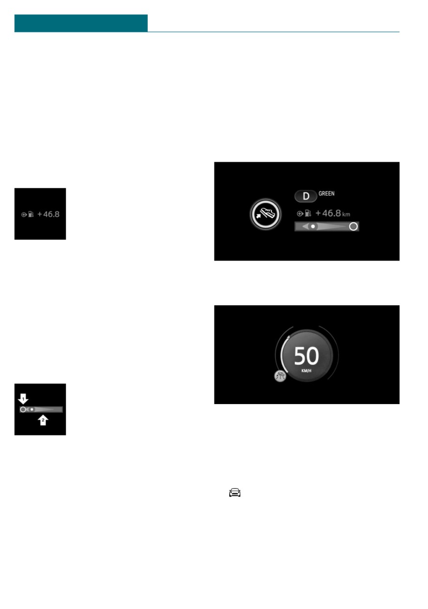
Efficiency display
A bar display in the instru-
ment cluster indicates your
current driving efficiency.
Mark in the left area, arrow 1:
Activating/deactivating the display
display for energy recovered
Activate information relating to the driving
by coasting or when braking.
style and GREEN tips in the instrument
Mark in the right area, arrow 2: display
cluster using the Central Information Dis-
when accelerating.
play (CID):
The efficiency of your driving style is
1.
"My MINI"
shown by the position of the mark:
2. "System settings"
- Mark inside the green range: efficient
driving style.
3. "Displays"
- Mark outside the green range: modify
4. "Instrument panel"
driving style, for example by backing off
5. "GREEN info"
the accelerator.
232
Reducing fuel consumption
DRIVING TIPS
GREEN tip, symbols
Displaying the MINIMALISM analyzer
An additional symbol and text instructions
Via the Central Information Display (CID):
are displayed.
1.
"My MINI"
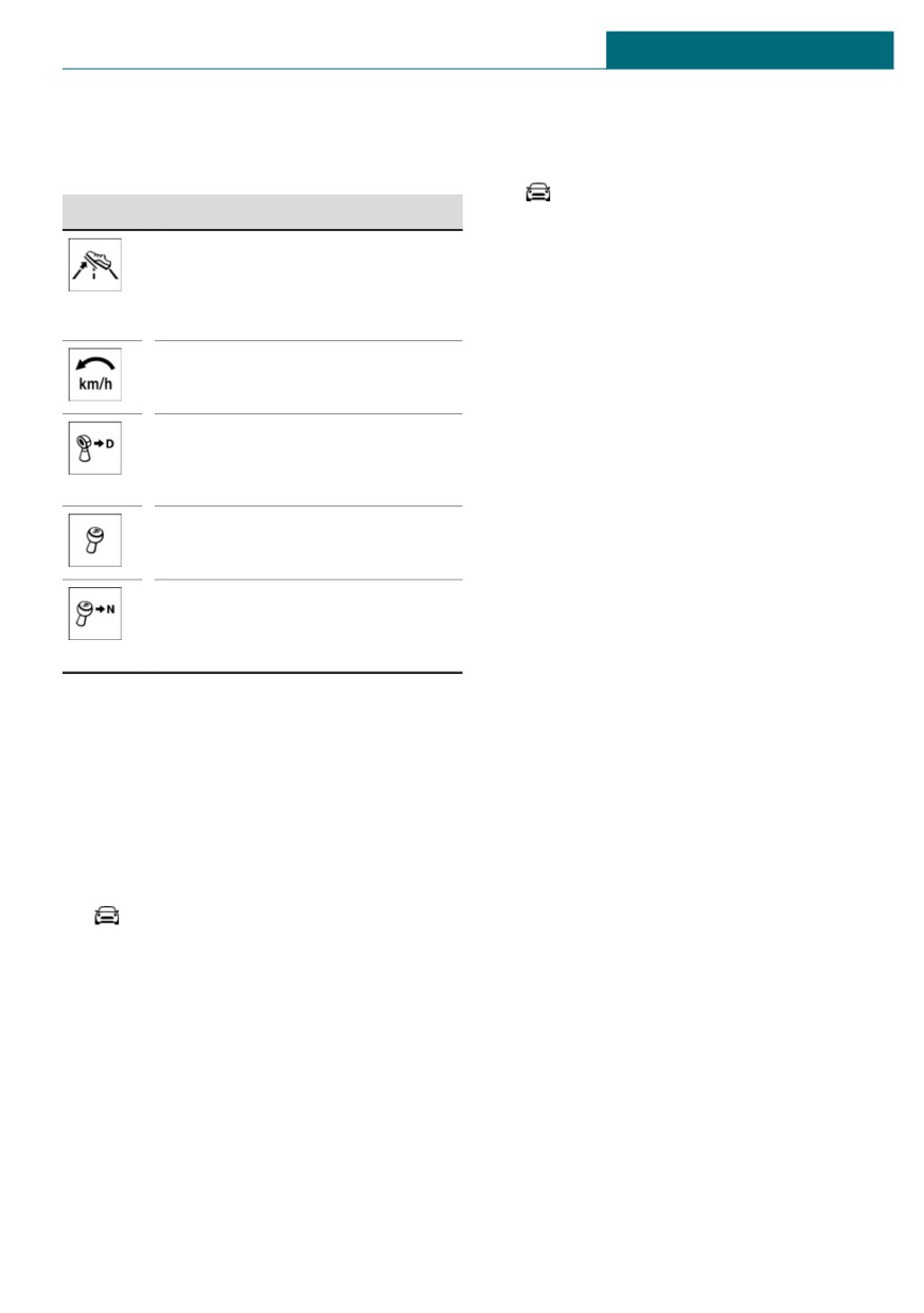
Symbol Measure
2. "Technology in action"
For an efficient driving style,
3. "MINIMALISM Analyser"
look well ahead when driving,
Further information on the MINIMALISM
accelerate conservatively, and
analyzer, refer to page 235.
delay accelerating.
Reduce speed to the selected
Coasting
GREEN speed.
Concept
Steptronic transmission:
The function helps to conserve fuel.
Switch from M/S to D and avoid
To do this, under certain conditions the en-
manual shift interventions.
gine is automatically decoupled from the
Manual transmission:
transmission when selector lever position D
Follow the shift instructions.
is set. The vehicle continues traveling with
the engine idling to reduce consumption.
Manual transmission:
Selector lever position D remains engaged.
Engage neutral for an engine
This driving condition is referred to as
stop.
coasting.
As soon as you step on the brake or acceler-
Indications on the Control Display
ator pedal, the engine is automatically cou-
pled again.
Displaying MINIMALISM information
General information
The current efficiency of the functions in
GREEN Mode can be displayed on the Con-
Coasting is a component of the GREEN driv-
trol Display.
ing mode.
Via the Central Information Display (CID):
Coasting is automatically activated when
the GREEN driving mode is called via the
1.
"My MINI"
MINI Driving Modes switch, refer to
2. "Technology in action"
page 172.
A proactive driving style helps the driver to
3. "MINIMALISM"
use the function often and supports the effi-
Information is shown on the following func-
cient effect of coasting.
tions:
- Auto Start/Stop function.
Functional requirements
- Energy recovery.
The function is available in the speed range
– Coasting.
from approx. 15 mph/25 km/h up to
100 mph/160 km/h.
- Accelerator pedal and brake pedal are
not operated.
233
DRIVING TIPS
Reducing fuel consumption
– The selector lever is in selector lever po-
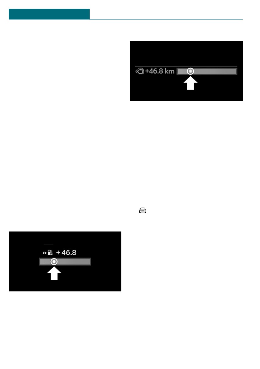
Instrument cluster with enhanced features
sition D.
- Engine and transmission are at operat-
ing temperature.
- With a camera in the area of the interior
mirror: the system does not detect any
vehicles ahead of you.
Operation via shift paddles
Concept
The bar display below the tachometer is fil-
Depending on your vehicle's equipment, the
led in green and the mark appears at the
coasting mode can be influenced with the
zero point. The tachometer indicates idle
shift paddles.
speed.
Activating/deactivating coasting via shift
Indications on the Control Display
paddles
The coasting driving condition is displayed
1. Shift to the highest gear by pulling the
in the MINIMALISM Info while driving.
right shift paddle.
The distance traveled in the coasting driv-
2. To activate coasting mode, actuate the
ing condition is indicated by a counter.
right shift paddle again.
To deactivate, actuate the left shift paddle.
Displaying MINIMALISM information
Via the Central Information Display (CID):
Display
1.
"My MINI"
Instrument cluster without enhanced
2. "Technology in action"
features
3. "MINIMALISM"
System limits
The function is not available if one of the
following conditions applies:
- DSC OFF and TRACTION are activated.
- Cruise control is activated.
- If driving in the dynamic limit range.
- If driving on steep uphill or downhill
The bar display below the tachometer is fil-
grades.
led in green and the mark appears at the
- The battery charge state is temporarily
zero point. The tachometer indicates idle
too low.
speed.
- The vehicle electrical system is drawing
excessive current.
234

Reducing fuel consumption
DRIVING TIPS
MINIMALISM analyzer
fish's mood worsens, and a reduced number
of stars is displayed.
Concept
The table of values contains stars and evalu-
ates the driving style in different catego-
The function helps develop an especially ef-
ries. The more efficient the driving style,
ficient driving style and to conserve fuel.
the more stars are displayed in the table.
For this purpose, the driving style is ana-
The bonus range achieved by a driving style
lyzed. The assessment is done in various
that minimizes consumption is displayed
categories and is displayed on the Control
below the table of values. The more effi-
Display.
cient the driving style, the faster the bonus
This display will help you adjust your driv-
range increases.
ing style and save some fuel.
To assist with an efficient driving style,
The range of the vehicle can be extended by
GREEN tips are displayed while driving.
adopting an efficient driving style. This gain
Tips for an energy-saving driving style, Sav-
in range is displayed as a bonus range in the
ing fuel, refer to page 229.
instrument cluster and on the Control Dis-
play.
Functional requirement
This function is available in GREEN Mode.
Displaying the MINIMALISM analyzer
Via the Central Information Display (CID):
1.
"My MINI"
2. "Technology in action"
3. "MINIMALISM Analyser"
Display on the Control Display
The display of the MINIMALISM analyzer
consists of a fish in a water glass, a table of
values and the display of the achieved bo-
nus range.
The fish and the movements of the water in
the bowl symbolize the efficiency of the
driving style.
Depending on the equipment, the fish is
shown with efficient and inefficient driving
style or only with inefficient driving style.
The more efficient the driving style, the less
the water sloshes around in the bowl and
the better is the fish's mood. If the driving
style is inefficient, the water oscillates, the
235
MOBILITY
Refueling
Refueling
Vehicle features and options
Fuel cap
This chapter describes all standard, country-
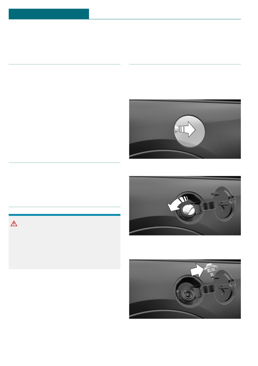
Opening
specific and optional features offered with
1. Grasp the fuel filler flap at the rear edge
the series. It also describes features and
and open it.
functions that are not necessarily available
in your vehicle, e.g., due to the selected op-
tions or country versions. This also applies
to safety-related functions and systems.
When using these functions and systems,
the applicable laws and regulations must be
observed.
General information
2. Turn the fuel cap counterclockwise.
Follow the fuel recommendation, refer to
page 238, prior to refueling.
Safety information
NOTICE
With a driving range of less than
30 miles/50 km the engine may no longer
3. Place the fuel cap in the bracket at-
have sufficient fuel. Engine functions are
tached to the fuel filler flap.
not ensured anymore. There is a risk of
damage to property. Refuel promptly.
236

Refueling
MOBILITY
Closing
Safety information
Warning
NOTICE
The retaining strap of the fuel cap can be
Fuels are toxic and aggressive. Overfilling
jammed and crushed during closing. The
of the fuel tank can damage the fuel sys-
cap cannot be correctly closed. Fuel or fuel
tem. Painted surfaces may be damaged by
vapors can escape. There is a risk of injury
contact with fuel. Escaping fuel can harm
or risk of damage to property. Pay atten-
the environment. There is a risk of damage
tion that the retaining strap is not jammed
to property. Avoid overfilling.
or crushed when closing the cap.
1. Fit the cap and turn it clockwise until
you clearly hear a click.
2. Press on the fuel filler flap until it en-
gages.
Emergency unlocking
It may be necessary in certain situations to
unlock the fuel filler flap manually, for in-
stance with an electrical fault.
Have fuel filler flap unlocked by a dealer’s
service center or another qualified service
center or repair shop.
Follow the following when re-
fueling
General information
When refueling, insert the filler nozzle
completely into the filler pipe. Lifting up the
fuel pump nozzle during refueling causes:
- Premature switching off.
- Reduced return of the fuel vapors.
The fuel tank is full when the filler nozzle
clicks off the first time.
Make sure that the fuel cap is closed prop-
erly after refueling, otherwise the emissions
warning light may light up.
Follow safety regulations posted at the gas
station.
237

MOBILITY
Fuel
Fuel
xx: comply with the current standard in
Vehicle features and options
each case.
This chapter describes all standard, country-
Safety information
specific and optional features offered with
the series. It also describes features and
functions that are not necessarily available
NOTICE
in your vehicle, e.g., due to the selected op-
Even small quantities of the wrong fuel or
tions or country versions. This also applies
wrong fuel additives can damage the fuel
to safety-related functions and systems.
system and engine. Furthermore, the cata-
When using these functions and systems,
lytic converter is permanently damaged.
the applicable laws and regulations must be
There is a risk of damage to property. Do
observed.
not refuel or add the following in the case
of gasoline engines:
- Leaded gasoline.
Fuel recommendation
- Metallic additives, for instance man-
ganese or iron.
General information
Do not press the Start/Stop button after
Depending on the region, many gas stations
refueling with the wrong fuel. Contact a
sell fuel that has been customized to winter
dealer’s service center or another qualified
or summer conditions. Fuel that is available
service center or repair shop.
in winter, for instance helps make a cold
start easier.
NOTICE
Gasoline
Incorrect fuels can damage the fuel system
and the engine. There is a risk of damage
General information
to property. Do not use fuels with a higher
For the best fuel efficiency, the gasoline
percentage of ethanol than recommended.
should be sulfur-free or very low in sulfur
Do not refuel with fuels containing metha-
content.
nol, e.g. M5 to M100.
Fuels that are marked on the gas pump as
containing metal must not be used.
Fuels with a maximum ethanol content of
NOTICE
25 %, i. e. E10 or E25, may be used for refu-
Fuel that does not comply with the mini-
eling.
mum quality can compromise engine func-
Ethanol should meet the following quality
tion or cause engine damage. There is a
standards:
risk of damage to property. Do not fill with
fuel that does not comply with the mini-
US: ASTM 4806-xx
mum quality.
CAN: CGSB-3.511-xx
238

Fuel
MOBILITY
CAUTION
The use of poor-quality fuels may result in
harmful engine deposits or damage. Addi-
tionally, problems relating to drivability,
starting and stalling, especially under cer-
tain environmental conditions such as
high ambient temperature and high alti-
tude, may occur.
If drivability problems are encountered,
we recommend switching to a high quality
gasoline brand and a higher octane grade
— AKI number — for a few tank fills. To
avoid harmful engine deposits, it is highly
recommended to purchase gasoline from
Top Tier retailers.
Failure to comply with these recommenda-
tions may result in the need for unsched-
uled maintenance.
Recommended fuel grade
MINI recommends AKI 91.
John Cooper Works:
MINI recommends AKI 93.
Refuel with this gasoline to achieve the
rated performance and consumption values.
Minimum fuel grade
MINI recommends AKI 89.
John Cooper Works:
MINI recommends AKI 91.
If you use gasoline with this minimum AKI
Rating, the engine may produce knocking
sounds when starting at high external tem-
peratures. This has no effect on the engine
life.
239
MOBILITY
Wheels and tires
Wheels and tires
Vehicle features and options
Tire inflation pressure
specifications
This chapter describes all standard, country-
specific and optional features offered with
In the tire inflation pressure table
the series. It also describes features and
The tire inflation pressure table, refer to
functions that are not necessarily available
page 242, contains all tire inflation pres-
in your vehicle, e.g., due to the selected op-
sure specifications for the specified tire
tions or country versions. This also applies
sizes at the ambient temperature. The tire
to safety-related functions and systems.
inflation pressure values apply to tire sizes
When using these functions and systems,
approved by the manufacturer of the vehicle
the applicable laws and regulations must be
for the vehicle type.
observed.
To identify the correct tire inflation pres-
sure, please note the following:
- Tire sizes of your vehicle.
Tire inflation pressure
- Maximum permitted driving speed.
General information
Checking the tire inflation pressure
The tire characteristics and tire inflation
pressure influence the following:
General information
- The service life of the tires.
Tires heat up while driving. The tire infla-
- Road safety.
tion pressure increases with the tire tem-
perature.
- Driving comfort.
Tires have a natural, consistent loss of tire
- Fuel consumption.
inflation pressure.
The displays of inflation devices may under-
Safety information
read by up to 0.1 bar/2 psi.
Warning
Checking using tire inflation pressure
A tire with too little or no tire inflation
specifications in the tire inflation
pressure may heat up significantly and
pressure table
sustain damage. This will have a negative
The tire inflation pressure specifications in
impact on aspects of handling, such as
the tire inflation pressure table only relate
steering and braking response. There is a
to cold tires or tires at the same tempera-
risk of accident. Regularly check the tire
ture as the ambient temperature.
inflation pressure, and correct it as
Only check the tire inflation pressure levels
needed, for instance twice a month and be-
when the tires are cold, i.e.:
fore a long trip.
- Driving range of max. 1.25 miles/2 km
has not been exceeded.
240

Wheels and tires
MOBILITY
– If the vehicle has not moved again for at
least 2 hours after a trip.
1. Determine the intended tire inflation
pressure levels for the mounted tires.
2. Check the tire inflation pressure in all
four tires, using a pressure gage, for ex-
ample.
3. Correct the tire inflation pressure if the
actual tire inflation pressure deviates
These pressure values can also be found on
from the intended tire inflation pres-
the tire inflation pressure label on the driv-
sure.
er's door pillar.
4. Check whether all valve caps are
screwed onto the tire valves.
Do not exceed a speed of 100 mph/
160 km/h.
After correcting the tire inflation
pressure
For run-flat tires: reinitialize run-flat tires.
For the Tire Pressure Monitor TPM: reset
the Tire Pressure Monitor TPM.
Checking the tire inflation pressure of
the emergency wheel
Also check the tire inflation pressure of the
emergency wheel in the cargo area regu-
larly, and correct it as needed.
Tire pressures up to 100 mph/
160 km/h
For speeds of up to 100 mph/160 km/h and
for optimum driving comfort, note the pres-
sure values in the tire inflation pressure ta-
ble, refer to page 242, and adjust as neces-
sary.
241
MOBILITY
Wheels and tires
Tire pressure values up to
COOPER S
100 mph/160 km/h
Tire size
Pressure specifica-
tions in bar/PSI
COOPER
Specifications
Tire size
Pressure specifica-
in bar/PSI with
tions in bar/PSI
cold tires
Specifications in
bar/PSI with cold
195/55 R 16 87
2.5 / 36
2.3 / 33
tires
V A/S
195/55 R 16 87
175/65 R 15 84
2.5 / 36
2.3 / 33
H M+S
H A/S
205/45 R 17 88
2.6 / 38
2.4 / 35
195/55 R 16 87
V XL A/S
V A/S
205/45 R 17 88
205/45 R 17 88
W XL
V XL A/S
205/45 R 17 88
195/55 R 16 87
V XL M+S
W
205/40 R 18 86
2.8 / 41
2.6 / 38
205/45 R 17 88
W XL
W XL
175/60 R 16 86
175/65 R 15 88
H XL M+S
H XL M+S
185/50 R 17 86
195/55 R 16 87
H XL M+S
H M+S
205/45 R 17 88
V XL M+S
205/40 R 18 86
2.7 / 39
2.5 / 36
W XL
175/60 R 16 86
H XL M+S
185/50 R 17 86
H XL M+S
242
Wheels and tires
MOBILITY
JOHN COOPER WORKS
Tire inflation pressure values over
100 mph/160 km/h
Tire size
Pressure specifications
in bar/PSI
COOPER
Specifications
in bar/PSI with
Tire size
Pressure specifica-
cold tires
tions in bar/PSI
Specifications in
bar/PSI with cold
205/45 R 17 88
2.8 / 41
2.5 / 36
tires
V XL A/S
205/45 R 17 88
W XL
175/65 R 15 84
2.8 / 41
2.6 / 38
205/40 R 18 86
H A/S
W XL
195/55 R 16 87
185/50 R 17 86
V A/S
H XL M+S
205/45 R 17 88
205/45 R 17 88
V XL A/S
V XL M+S
195/55 R 16 87
W
Tire inflation pressures at max.
205/45 R 17 88
W XL
speeds above 100 mph/160 km/h
175/65 R 15 88
H XL M+S
Warning
195/55 R 16 87
In order to drive at maximum speeds in ex-
H M+S
cess of 100 mph/160 km/h, please ob-
205/45 R 17 88
serve, and, if necessary, adjust tire pres-
V XL M+S
sures for speeds exceeding 100 mph/
160 km/h from the relevant table on the
205/40 R 18 86
3.0 / 44
2.7 / 39
following pages. Otherwise, tire damage
W XL
and accidents could occur.
175/60 R 16 86
H XL M+S
For speeds over 100 mph/160 km/h and for
185/50 R 17 86
optimum driving comfort, note the pressure
H XL M+S
values in the tire inflation pressure table,
refer to page 243, and adjust as necessary.
243