MINI Convertible (2021 year). Manual in english - page 4
CONTROLS
Driving
within approx. 15 minutes, the rain sensor
is automatically activated again.
NOTICE
When the washer fluid reservoir is empty,
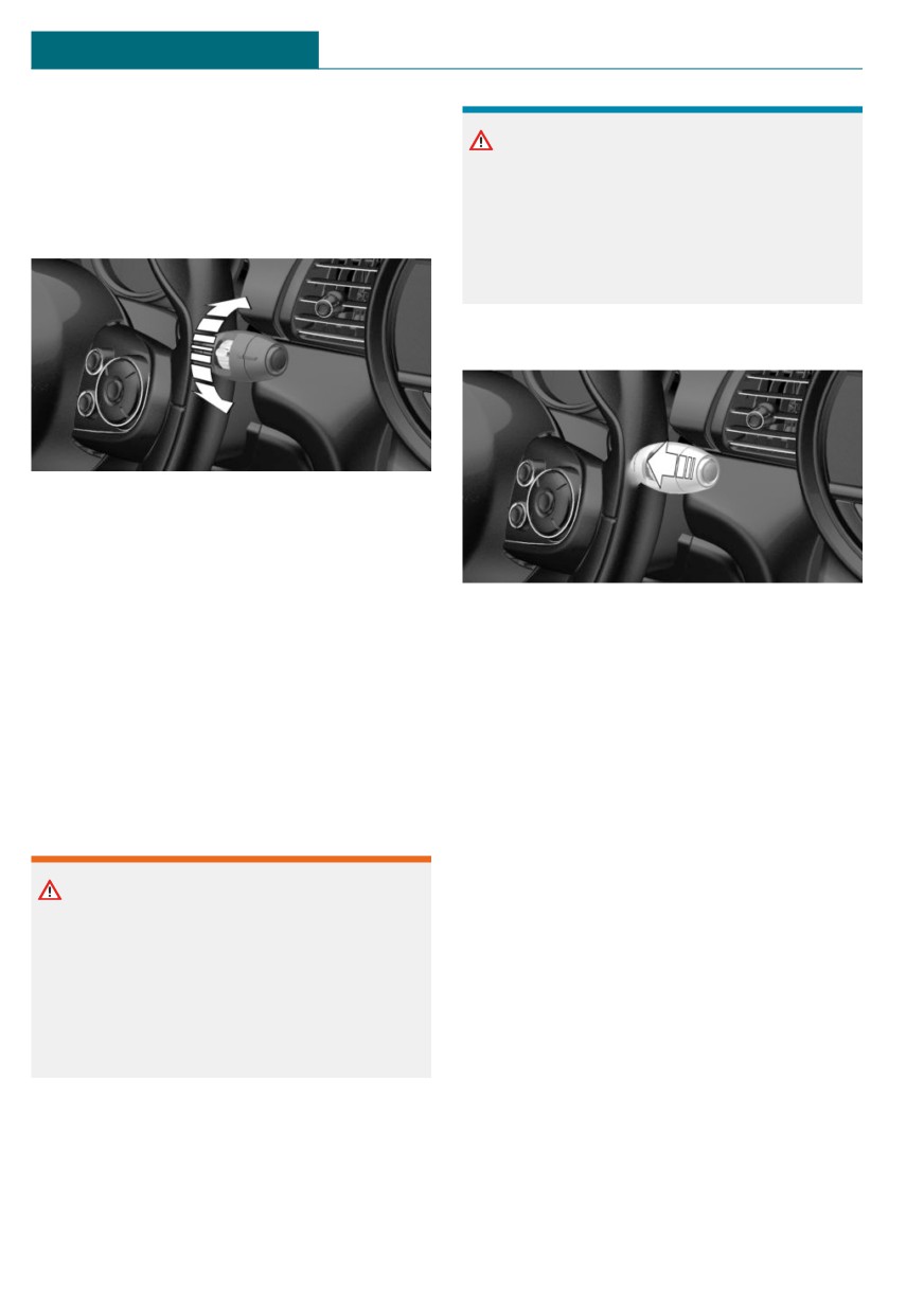
Setting the frequency or sensitivity of
the wash pump cannot work as intended.
There is a risk of damage to property. Do
the rain sensor
not use the washer system when the
washer fluid reservoir is empty.
Cleaning the windshield
Turn the thumbwheel.
With deactivated rain sensor: set the inter-
val.
With activated rain sensor: set the rain sen-
sor sensitivity.
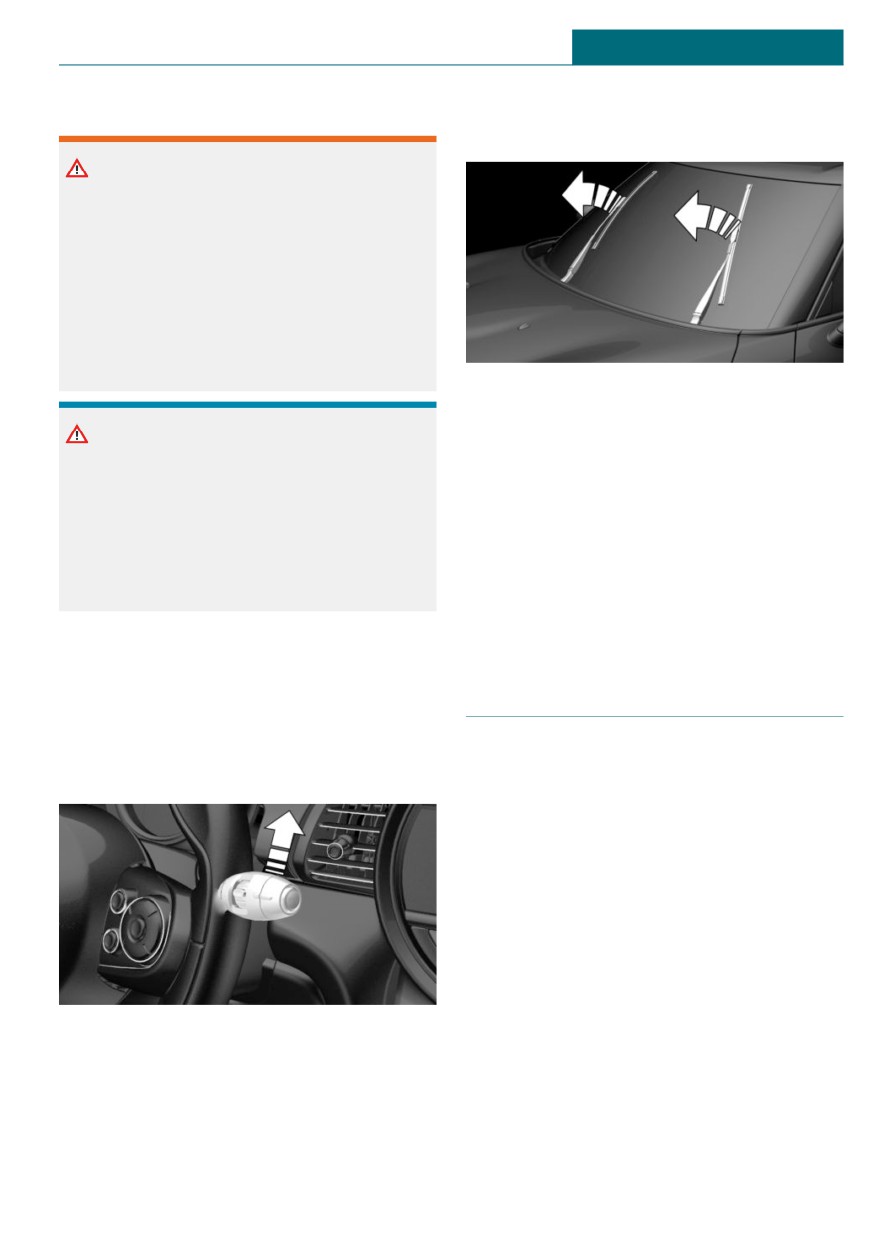
Pull the lever.
Up: short interval or high sensitivity of the
The system sprays washer fluid on the
rain sensor.
windshield and activates the wipers briefly.
Down: long interval or low sensitivity of the
rain sensor.
Windshield washer nozzles
The washer jets are automatically heated
Windshield washer system
whenever the ignition is switched on.
Safety information
Fold-away position of the wipers
Concept
Warning
The fold-away position enables the wipers
The washer fluid can freeze onto the win-
to be folded away from the windshield.
dow at low temperatures and obstruct the
view. There is a risk of accident. Only use
General information
the washer systems, if the washer fluid
cannot freeze. Use washer fluid with anti-
Helpful when changing the wiper blades or
freeze, if needed.
under frosty conditions, for instance.
108
Driving
CONTROLS
Safety information
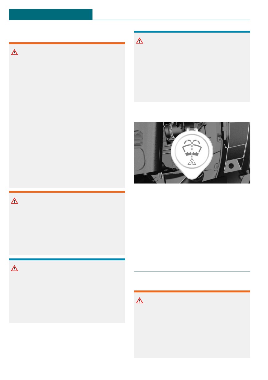
3. Fold the wipers all the way away from
the windshield.
Warning
If the wipers start moving in the folded
away state, body parts can be jammed or
damage may occur to parts of the vehicle.
There is a risk of injury or risk of damage
to property. Make sure that the vehicle is
switched off when the wipers are in the
folded away state and the wipers are
folded in when switching on.
Folding down the wipers
NOTICE
After the wipers are folded back down, the
wiper system must be reactivated.
If the wipers are frozen to the windshield,
the wiper blades can be torn off and the
1. Fold the wipers back down onto the
wiper motor can overheat when switching
windshield.
on. There is a risk of damage to property.
2. Switch on the ignition.
Defrost the windshield prior to switching
the wipers on.
3. Push wiper lever down. Wipers return
to their resting position and are ready
again for operation.
Folding away the wipers
1. Switch the ignition on and off again.
Washer fluid
2. Press the wiper lever up past the point
of resistance and hold it for approx.
3 seconds, until the wipers remain in a
General information
nearly vertical position.
All washer nozzles are supplied from one
reservoir.
Use a mixture of tap water and windshield
washer concentrate. If desired, a windshield
washer concentrate containing antifreeze
can be used.
Recommended minimum fill quantity:
0.2 US gal/1 liter.
109
CONTROLS
Driving
Safety information
NOTICE
Mixing different windshield washer con-
Warning
centrates or antifreeze can damage the
Some antifreeze agents can contain harm-
washing system. There is a risk of damage
ful substances and are flammable. There is
to property. Do not mix different wind-
a risk of fire and a risk of injury. Follow
shield washer concentrates or antifreeze.
the instructions on the containers. Keep
Follow the information and mixing ratios
antifreeze away from ignition sources. Do
provided on the containers.
not refill operating materials into different
bottles. Store operating materials out of
reach of children.
Overview
United States: the washer fluid mixture ra-
tio is regulated by the U.S. EPA and many
individual states; do not exceed the allow-
able washer fluid dilution ratio limits that
apply. Follow the usage instructions on the
washer fluid container.
Use of BMW’s Windshield Washer Con-
centrate or the equivalent is recom-
mended.
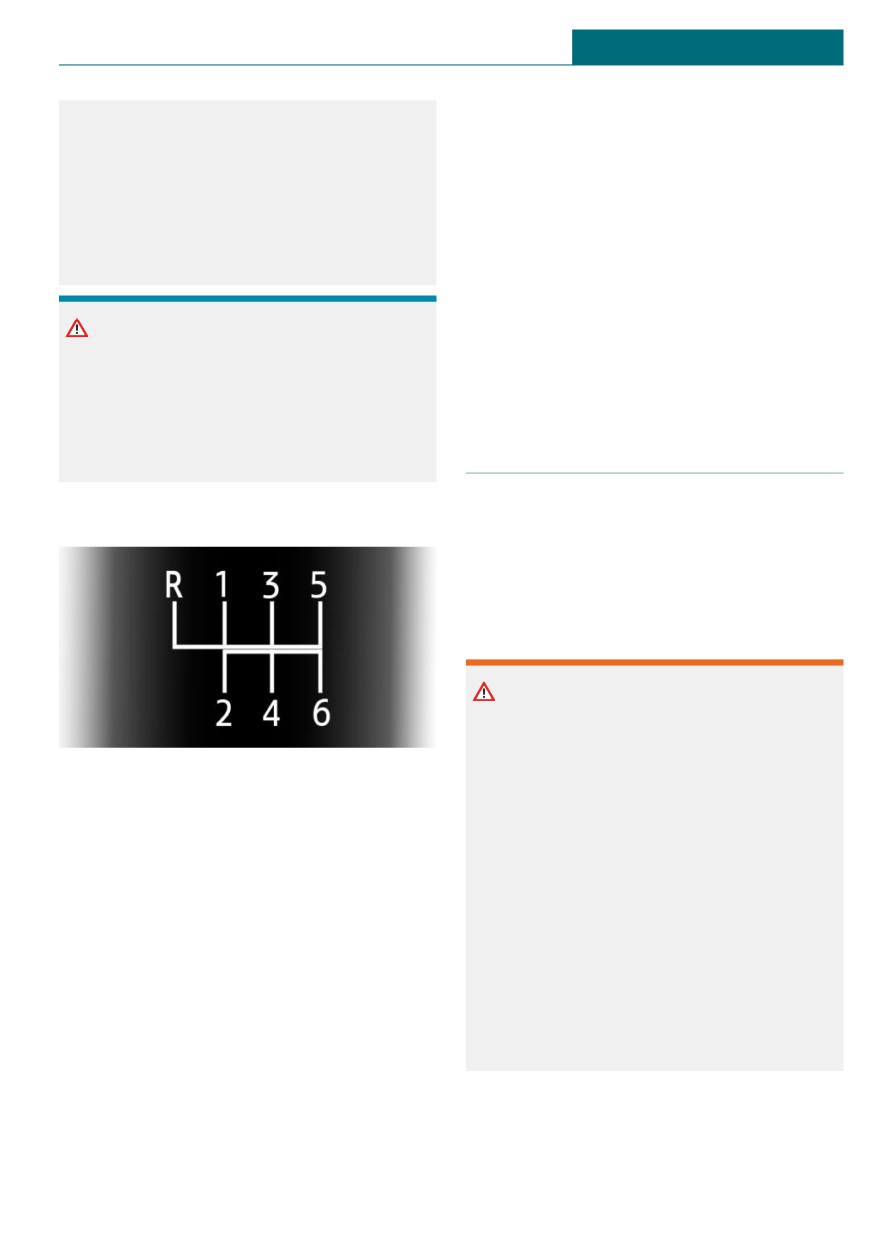
The washer fluid reservoir is located in the
engine compartment.
Warning
Washer fluid can ignite and catch fire on
Malfunction
contact with hot engine parts. There is a
The use of undiluted windshield washer
risk of injury or risk of damage to prop-
concentrate or alcohol-based antifreeze can
erty. Only add washer fluid when the en-
lead to incorrect readings at temperatures
gine is cooled down. Next, fully close the
below +5 ℉/-15 ℃.
lid of the washer fluid reservoir.
Manual transmission
NOTICE
Silicon-containing additives in the washer
Safety information
fluid for the water-repelling effect on the
windows can lead to damage to the wash-
ing system. There is a risk of damage to
Warning
property. Do not add silicon-containing ad-
An unsecured vehicle can begin to move
ditives to the washer fluid.
and possibly roll away. There is a risk of
accident. Before exiting, secure the vehi-
cle against rolling.
In order to ensure that the vehicle is se-
cured against rolling away, follow the fol-
lowing:
110
Driving
CONTROLS
– Set the parking brake.
gage reverse gear with a forward shifting
movement.
– On uphill grades or on a downhill
slope, turn the front wheels in the di-
rection of the curb.
Rolling or pushing the vehicle
- On uphill grades or on a downhill
In some situations, the vehicle is to roll
slope, also secure the vehicle, for in-
without its own power, for instance in a car
stance with a wheel chock.
wash, or be pushed.
1. Switch on the ignition.
NOTICE
2. Press on the clutch pedal and shift out
of a forward gear or reverse.
When shifting to a lower gear, excessive
speeds can damage the engine. There is a
3. Release the parking brake.
risk of damage to property. When shifting
into 5th or 6th gear, press the gearshift
lever to the right.
Steptronic transmission
Concept
Schematic diagram
The Steptronic transmission combines the
functions of an automatic transmission with
the possibility of manual shifting, if needed.
Safety information
Warning
An unsecured vehicle can begin to move
and possibly roll away. There is a risk of
-
1-6: forward gears.
accident. Before exiting, secure the vehi-
cle against rolling.
–
R: reverse gear.
In order to ensure that the vehicle is se-
cured against rolling away, follow the fol-
Shifting
lowing:
- Set the parking brake.
General information
- On uphill grades or on a downhill
Depending on the engine installation, the
slope, turn the front wheels in the di-
engine speed during a shifting operation is
rection of the curb.
adjusted automatically as required for har-
- On uphill grades or on a downhill
monious and dynamic gear shifting.
slope, also secure the vehicle, for in-
stance with a wheel chock.
Reverse gear
Select only when the vehicle is stationary.
To overcome the resistance push the gear-
shift lever dynamically to the left and en-
111
CONTROLS
Driving
Selector lever version
or, in certain situations, automatically, refer
to page 112.
General information
Depending on the vehicle equipment, a
Selector lever positions
transmission with either a latching selector
lever or a tap-operated selector lever is in-
Drive mode D
stalled.
Selector lever position for normal vehicle
operation. All gears for forward travel are
Transmission with a latching selector
activated automatically.
lever
R is reverse
Engage selector lever position R only when
the vehicle is stationary.
Neutral N
The vehicle may be pushed or roll without
engine power in selector lever position N,
for instance in vehicle washes, refer to
page 114.
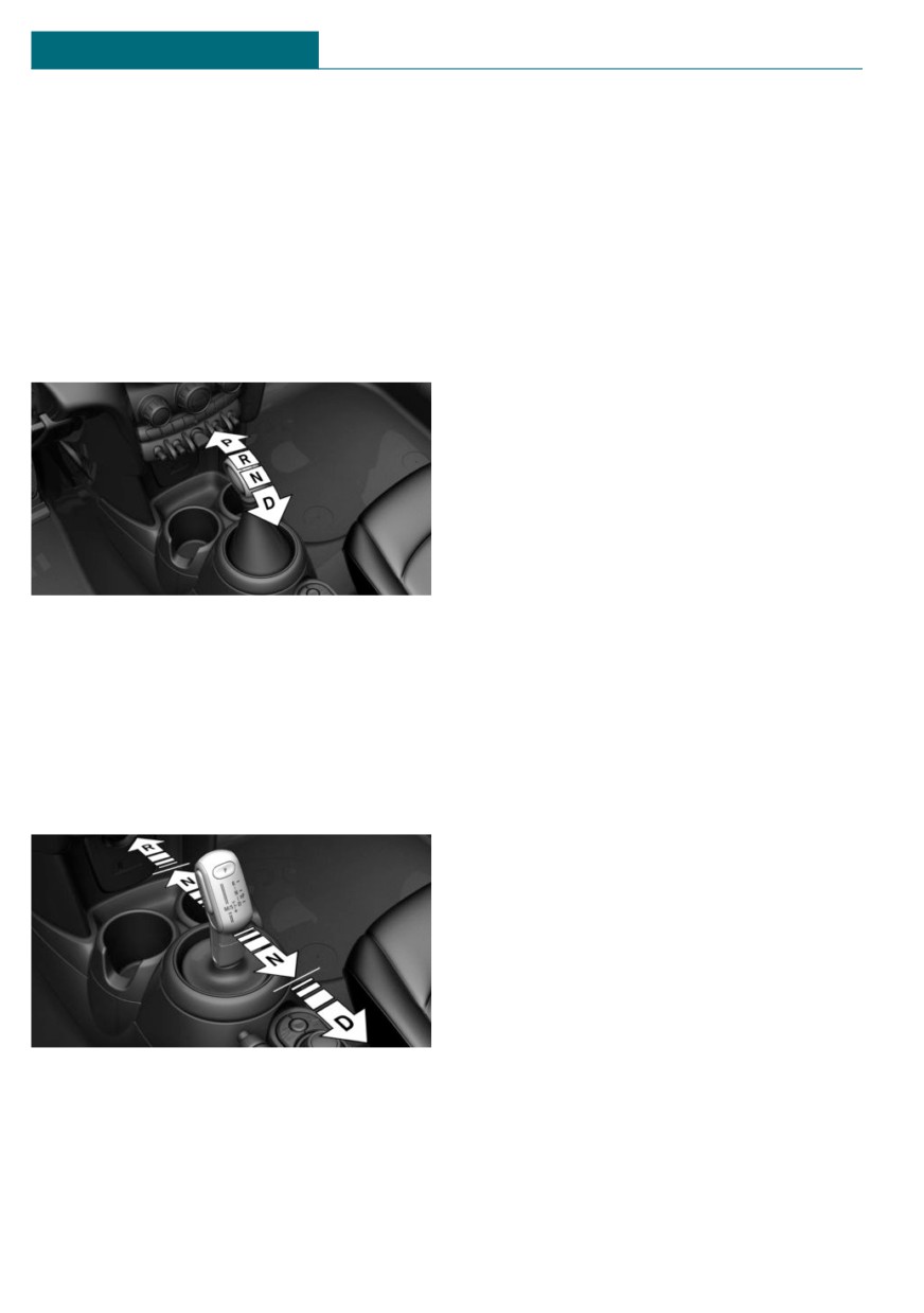
The selector lever positions P, R, N, and D
are selected by moving the selector lever
Parking position P
into the respective selector lever position.
The selector lever engages in the selector
General information
lever positions.
Selector lever position, for instance for
parking the vehicle.
Transmission with a tap-operated
The transmission blocks the drive wheels in
selector lever
selector lever position P.
Engage selector lever position P only when
the vehicle is stationary.
Before exiting the vehicle, make sure that
selector lever position P is set. Otherwise,
the vehicle may begin to move.
Automatic parking position for a
transmission with a tap-operated selector
lever
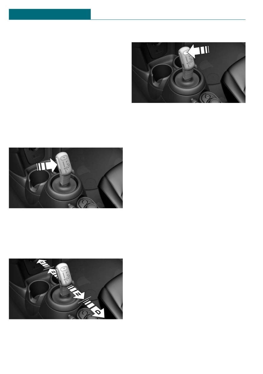
The selector lever positions R, N, and D are
Selector lever position P is engaged auto-
selected by tapping the selector lever for-
matically in situations such as the follow-
ward or back. The selector lever automati-
ing:
cally returns to the center position when re-
- After the engine is switched off when
leased.
the vehicle is in the radio-ready state,
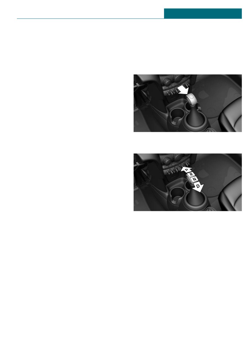
The selector lever position P is engaged by
refer to page 97, or when the ignition is
pressing the P button on the selector lever
switched off, refer to page 96, while se-
112
Driving
CONTROLS
lector lever position R, D or M/S is en-
–
Unintentional shifting from selector
gaged.
lever position P into another selector
lever position.
- If the driver's safety belt is unbuckled,
the driver's door is opened, and the
1.
To release the selector lever lock: with
brake pedal is not pressed while the ve-
the brake pedal depressed, press the
hicle is stationary and selector lever po-
button on the front of the selector lever.
sition D, M/S or R is engaged.
- After the ignition has been switched off
while selector lever position N is en-
gaged.
Engaging selector lever positions:
with a latching selector lever
General information
To prevent the vehicle from creeping after
2.
Move the selector lever into the desired
you select a drive mode, maintain pressure
position.
on the brake pedal until you are ready to
start.
Functional requirements
The selector lever can only be taken out of
selector lever position P if the ignition is on
or the engine is running.
Engaging selector lever position D, N,
R, or P
With the vehicle stationary, depress the
Engaging selector lever positions:
brake pedal before shifting out of selector
with a tap-operated selector lever
lever position P or N; otherwise, the shift
block will not be deactivated and the shift
General information
command will not be executed.
To prevent the vehicle from creeping after
A selector lever lock prevents the following
you select a drive mode, maintain pressure
faulty operation:
on the brake pedal until you are ready to
- Unintentional shifting into selector
start.
lever position P or R.
Functional requirements
Only when the brake pedal is depressed is it
possible to change from selector lever posi-
tion P to another selector lever position.
Depending on the transmission version, the
engine may have to be running too.
113
CONTROLS
Driving
The selection lever position P cannot be
Engaging selector lever position P
changed until all technical requirements are
met.
Engaging selector lever position D, N,
R
A selector lever lock prevents the following
faulty operation:
-
Unintentional shifting into selector
lever position R.
-
Unintentional shifting from selector
Press button P.
lever position P into another selector
lever position.
Rolling or pushing the vehicle
1.
Press and hold the button to release the
selector lever lock.
General information
In some situations, the vehicle is to roll
without its own power for a short distance,
for instance in a car wash, or be pushed.
Engaging selector lever position N:
with a latching selector lever
1. Switch on the ignition.
2. If necessary, release the parking brake.
2.
With the driver's safety belt fastened,
3. Depress the brake pedal.
briefly push the selector lever in the de-
4. Touch the selector lever lock and en-
sired direction, past a resistance point,
gage selector lever position N.
if needed. The selector lever automati-
5. Release brake.
cally returns to the center position when
released.
The vehicle can roll.
If there is a malfunction, you may not be
able to change the selector lever position.
Manually unlock the transmission lock, if
needed, refer to page 117.
Engaging selector lever position N:
with a tap-operated selector lever
1. Start the engine while pressing on the
brake pedal.
2. If necessary, release the parking brake.
3. Depress the brake pedal.
114
Driving
CONTROLS
4. Touch the selector lever lock and en-
Activating the Sport program
gage selector lever position N.
5. Switch the engine off.
In this way, the ignition remains
switched on, and a Check Control mes-
sage is displayed.
The vehicle can roll.
NOTICE
Selector lever position P is automatically
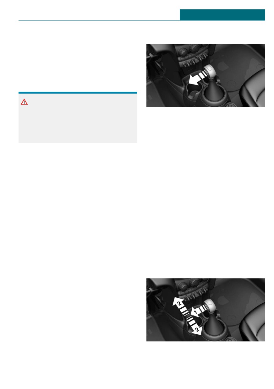
Press the selector lever to the left from se-
engaged when the ignition is switched off.
lector lever position D.
There is a risk of damage to property. Do
The engaged gear is displayed in the instru-
not switch ignition off in vehicle washes.
ment cluster, for instance S1.
Irrespective of the ignition, the selector
The sport program of the transmission is ac-
lever position P is automatically engaged af-
tivated.
ter approx. 15 minutes.
If there is a malfunction, you may not be
Ending the Sport program
able to change the selector lever position.
Push the selector lever to the right.
Electronically unlock the transmission lock,
D is displayed in the instrument cluster.
if needed, refer to page 117.
Manual mode M/S
Kickdown
Kickdown is used to achieve maximum driv-
Concept
ing performance. Step on the accelerator
Manual gear-shifting is possible in manual
pedal beyond the resistance point at the full
mode.
throttle position.
Activating manual mode
Sport program M/S
1. Press the selector lever to the left from
selector lever position D, arrow 1.
Concept
The shifting points and shifting times in the
Sport program are designed for a sportier
driving style. The transmission, for instance
shifts up later and the shifting times are
shorter.
2. Push the selector lever forward or pull it
backward, arrows 2.
115
CONTROLS
Driving
Manual mode M/S becomes active and the
Ending the manual mode
gear is changed.
Push the selector lever to the right.
The engaged gear is displayed in the instru-
D is displayed in the instrument cluster.
ment cluster, for instance M1.
Shift paddles for Steptronic Sport
Shifting
transmission
- To shift down: press the selector lever
forward.
Concept
- To shift up: pull the selector lever rear-
The shift paddles on the steering wheel al-
wards.
low you to shift gears quickly while keeping
The Steptronic transmission continues
both hands on the steering wheel.
shifting automatically in certain situations,
for instance when certain engine speed lim-
General information
its are reached.
With a tap-operated selector lever: when
Shifting
M2 is set manually while the vehicle is sta-
Gears will only be shifted at appropriate en-
tionary, the transmission will no longer
gine and road speeds, for instance down-
shift back to M1. This shifting behavior is
shifting is not possible if the engine speed
retained until you engage M1 manually or
is too high.
exit M.
Short-term manual mode
Avoiding automatic upshifting
In selector lever position D, actuating a
Once a particular engine speed is attained,
shift paddle switches into manual mode
M/S manual mode is automatically up-
temporarily.
shifted as needed.
After conservative driving in manual mode
John Cooper Works: once particular engine
without acceleration or shifting via the shift
speeds are attained, upshifting is not auto-
paddles for a certain amount of time, the
matically performed in M/S manual mode.
transmission switches back to automatic
For vehicles with Steptronic Sport transmis-
mode.
sion, automatic shift operations are not per-
It is possible to switch into automatic mode
formed if one of the following conditions is
as follows:
met:
- Keep the right shift paddle pulled until
- DSC is deactivated.
D is displayed in the instrument cluster.
- TRACTION is activated.
- In addition to the pulled right shift pad-
In addition, there is no downshifting for
dle, pull the left shift paddle.
kickdown.
Continuous manual mode
With the appropriate transmission version,
the lowest possible gear can be selected by
In selector lever position S, actuating a shift
simultaneously activating kickdown and op-
paddle switches into manual mode perma-
erating the left shift paddles. This is not
nently.
possible by switching briefly via the shift
paddles from selector lever position D to
manual mode M/S.
116
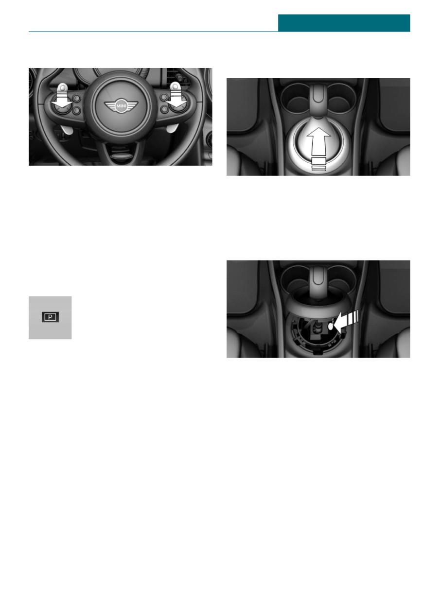
Driving
CONTROLS
Shifting
the retaining ring upward at the rear
edge.
- Shifting up: pull the right shift paddle.
2. Lift the sleeve. Unplug the cable connec-
- Shifting down: pull left shift paddle.
tor, if needed.
- Downshifting to the lowest possible
3. Using the screwdriver from the onboard
gear: keep the left shift paddle pulled.
vehicle tool kit, refer to page 272, press
The selected gear is briefly displayed in the
the yellow release lever downward, see
instrument cluster, followed by the current
arrow.
gear.
Displays in the instrument cluster
The selector lever position is
displayed, for example P.
Releasing the transmission lock
4. Press the button on the front of the se-
manually: with a latching selector
lector lever and move the selector lever
lever
back slightly.
If the selector lever is locked in selector
Release the release lever.
lever position P despite the ignition being
5. Bring the selector lever into the desired
switched on, the brake pedal being de-
position.
pressed and the button on the selector lever
being pressed, the transmission lock can be
For additional information, see the chapter
unlocked manually:
on tow-starting and towing.
Before unlocking the transmission lock
manually, engage the parking brake force-
Releasing the transmission lock
fully to prevent the vehicle from rolling
electronically: with a tap-operated
away.
selector lever
1. Loosen the selector lever sleeve, to-
gether with the lower retaining ring,
General information
from the center console. To do so, pull
Electronically unlock the transmission lock
to maneuver vehicle from a danger area.
117
CONTROLS
Driving
Before unlocking the transmission lock, set
General information
the parking brake to prevent the vehicle
The use of Launch Control causes prema-
from rolling away.
ture component wear since this function
represents a very heavy load for the vehicle.
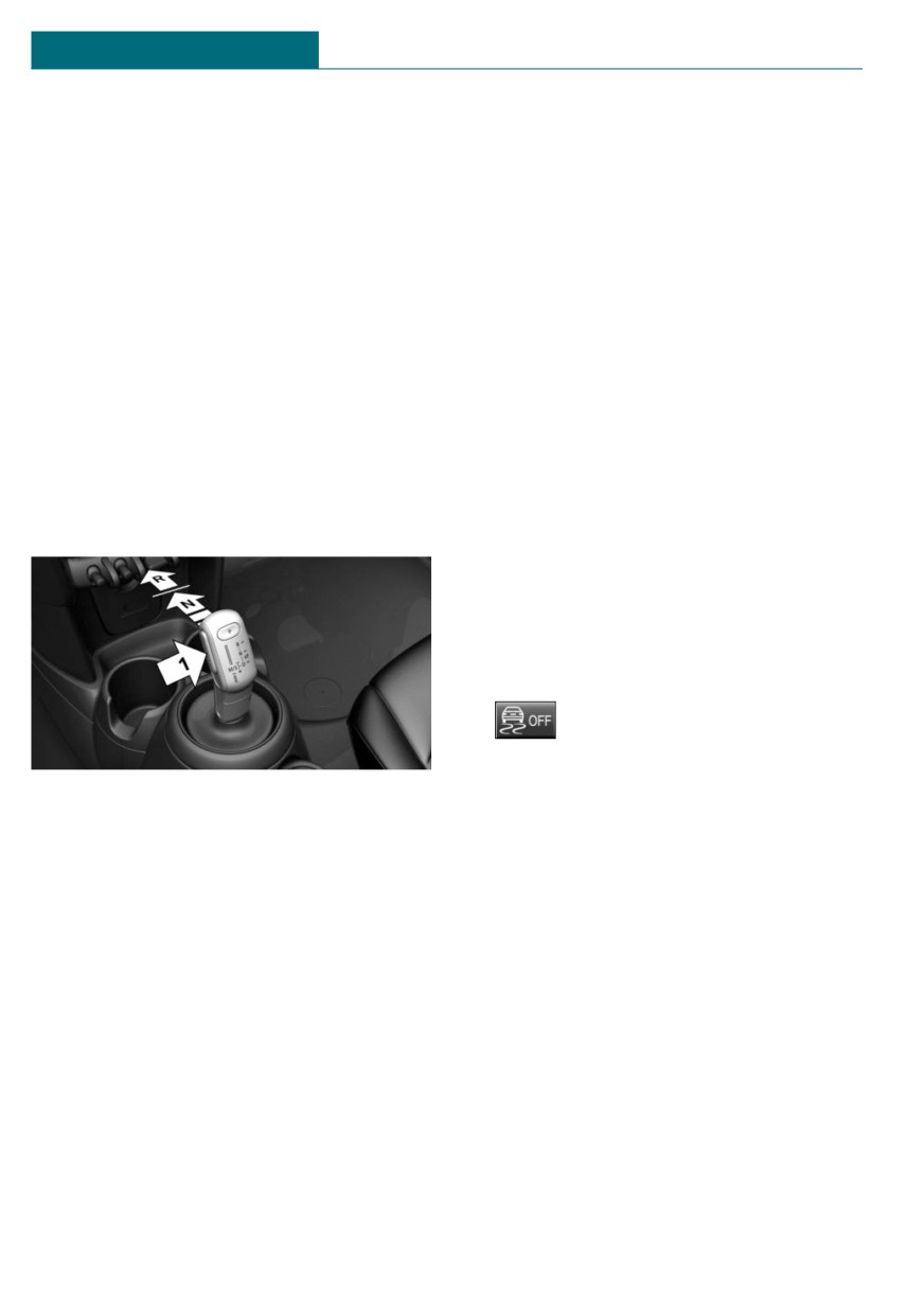
Engaging selector lever position N
Do not use Launch Control during the
Unlocking is possible, if the starter can spin
break-in, refer to page 224, period.
the engine.
Do not turn the steering wheel when driv-
1.
Press and hold down brake pedal.
ing away with Launch Control.
2.
Press the Start/Stop button. The starter
Functional requirements
must audibly start.
Launch Control is available as soon as the
3.
Press the button on the selector lever,
engine and transmission are at operating
arrow 1, and press and hold the selector
temperature.
lever into selector lever position N, ar-
row N, until selector lever position N is
Depending on the external temperature and
displayed in the instrument cluster.
driving style, the engine and transmission
require an interrupted trip of up to
A Check Control message is displayed.
30 miles/50 km in order to reach the oper-
ating temperature needed for Launch Con-
trol.
Start with launch control
While the engine is running:
1.
Press button and select SPORT
with the MINI Driving Modes switch.
The instrument cluster displays TRAC-
4.
Release the selector lever.
TION in combination with SPORT. The
5.
Release brake, as soon as the starter
DSC OFF indicator light lights up.
stops.
2.
Engage selector lever position S.
6.
Maneuver the vehicle from the danger
3.
With the left foot, forcefully press down
area and secure it against moving on its
on the brake.
own.
4.
Press and hold down the accelerator
For additional information, see the chapter
pedal beyond the resistance point at the
on tow-starting and towing.
full throttle position, kickdown.
A flag symbol is displayed in the instru-
Steptronic Sport transmission:
ment cluster.
Launch Control
5.
The starting engine speed adjusts. Wait
briefly until the engine speed is con-
Concept
stant. Keep accelerator pedal in this po-
Launch Control enables optimum accelera-
sition.
tion on surfaces with good traction under
6.
Release the brake within 3 seconds after
dry surrounding conditions.
the flag symbol illuminates.
118
Driving
CONTROLS
The vehicle accelerates.
Upshifting occurs automatically as long
as the flag symbol is displayed and the
accelerator pedal is not released.
Repeated use during a trip
After Launch Control has been used, the
transmission must cool down for approx.
5 minutes before Launch Control can be
used again.
After using Launch Control
To increase vehicle stability, activate DSC
Dynamic Stability Control again.
System limits
An experienced driver may be able to ach-
ieve better acceleration values in DSC OFF
mode.
119
CONTROLS
Displays
Displays
in your vehicle, e.g., due to the selected op-
Vehicle features and options
tions or country versions. This also applies
to safety-related functions and systems.
This chapter describes all standard, country-
When using these functions and systems,
specific and optional features offered with
the applicable laws and regulations must be
the series. It also describes features and
observed.
functions that are not necessarily available
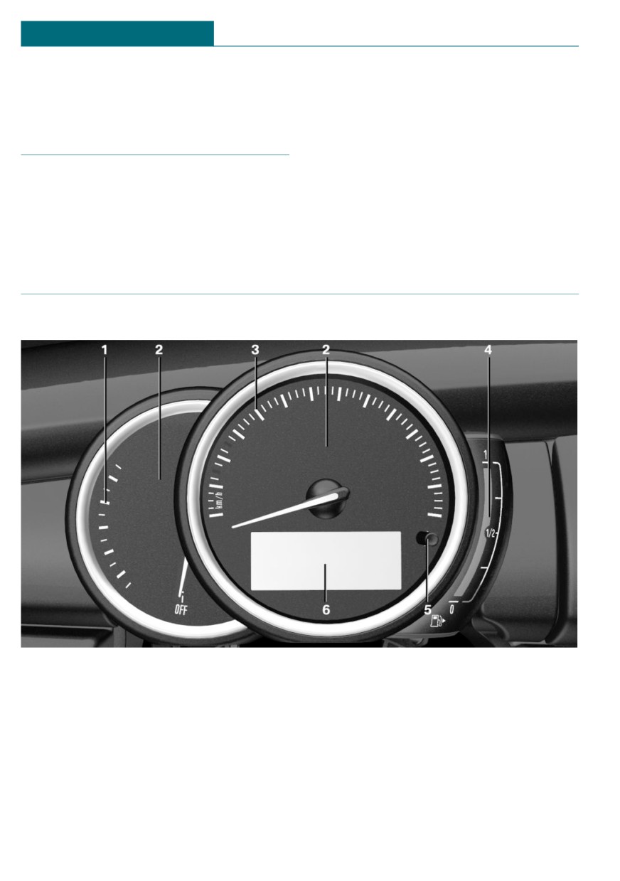
Instrument cluster
Instrument cluster without enhanced features: overview
1
Tachometer
127
4
Fuel gauge
127
2
Indicator/warning lights
5
Display/reset miles
127
3
Speedometer
6
Electronic displays
122
120
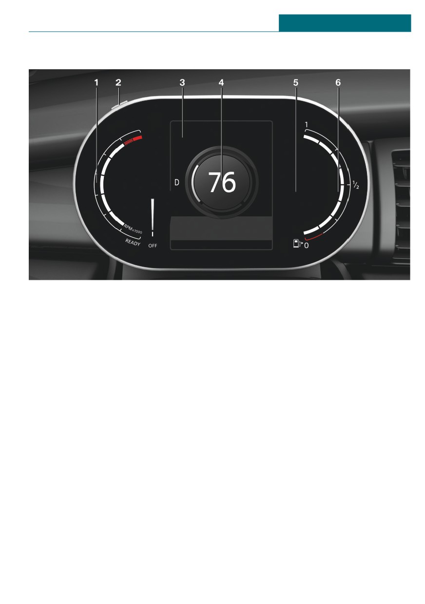
Displays
CONTROLS
Instrument cluster with enhanced features: overview
1
Tachometer
127
4
Vehicle speed
2
Display/reset miles
127
5
Indicator/warning lights
3
Electronic displays
123
6
Fuel gauge
127
121
CONTROLS
Displays
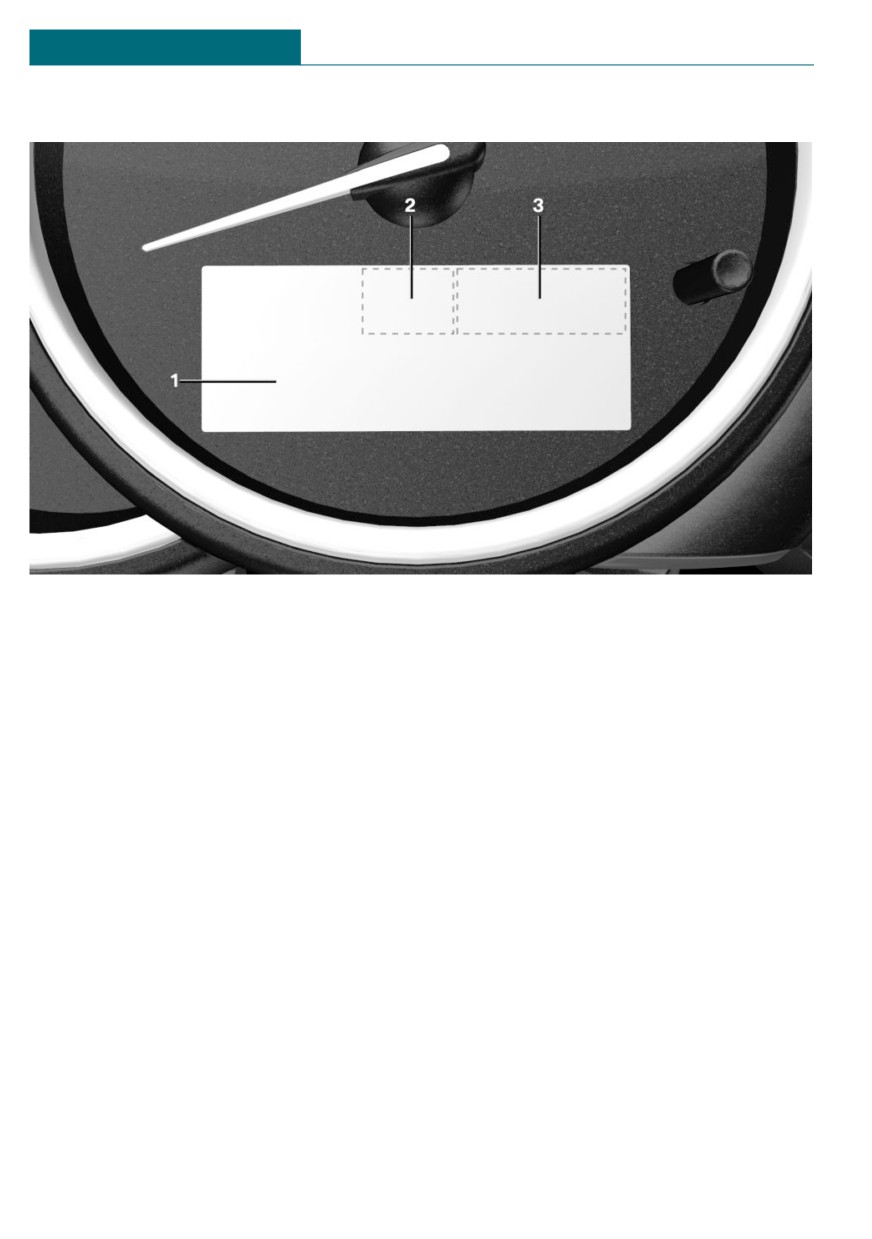
Instrument cluster without additional functions: electronic displays
1
Driver assistance systems
Onboard Computer
133
Messages, for instance Check Control
2
Selector lever position
111
Time
128
Gear shift indicator
130
External temperature
128
3
MINI Driving Modes switch sta-
tus
172
Selection lists
132
Total miles/trip odometer
127
122
Displays
CONTROLS
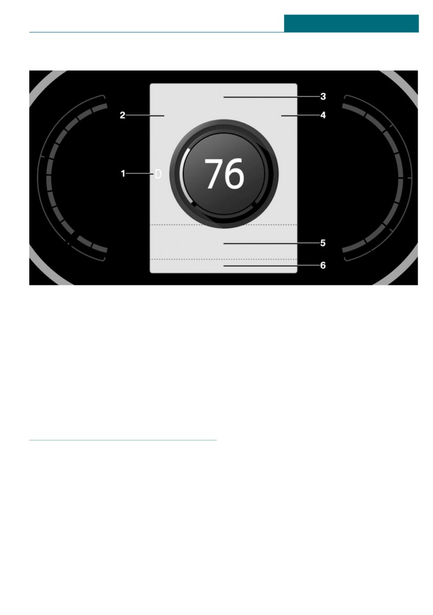
Instrument cluster with enhanced features: electronic displays
1
Selector lever position
111
5
Messages, for instance Check Control
Gear shift indicator
130
Selection lists
132
2
Time
128
Navigation instructions
MINI Driving Modes switch sta-
6
Total miles/trip odometer
127
tus
172
Onboard Computer
133
3
Driver assistance systems
4
External temperature
128
Range
128
In addition, an acoustic signal may be out-
Check Control
put and a SMS text message may appear on
the Control Display.
Concept
The Check Control system monitors func-
Indicator/warning lights
tions in the vehicle and notifies you of mal-
functions in the monitored systems.
General information
The indicator/warning lights can light up in
General information
a variety of combinations and colors.
A Check Control message is displayed as a
Several of the lights are checked for proper
combination of indicator or warning lights
functioning and light up temporarily when
and text messages in the instrument cluster
the engine is started or the ignition is
and in the Head-up Display.
switched on.
123
CONTROLS
Displays
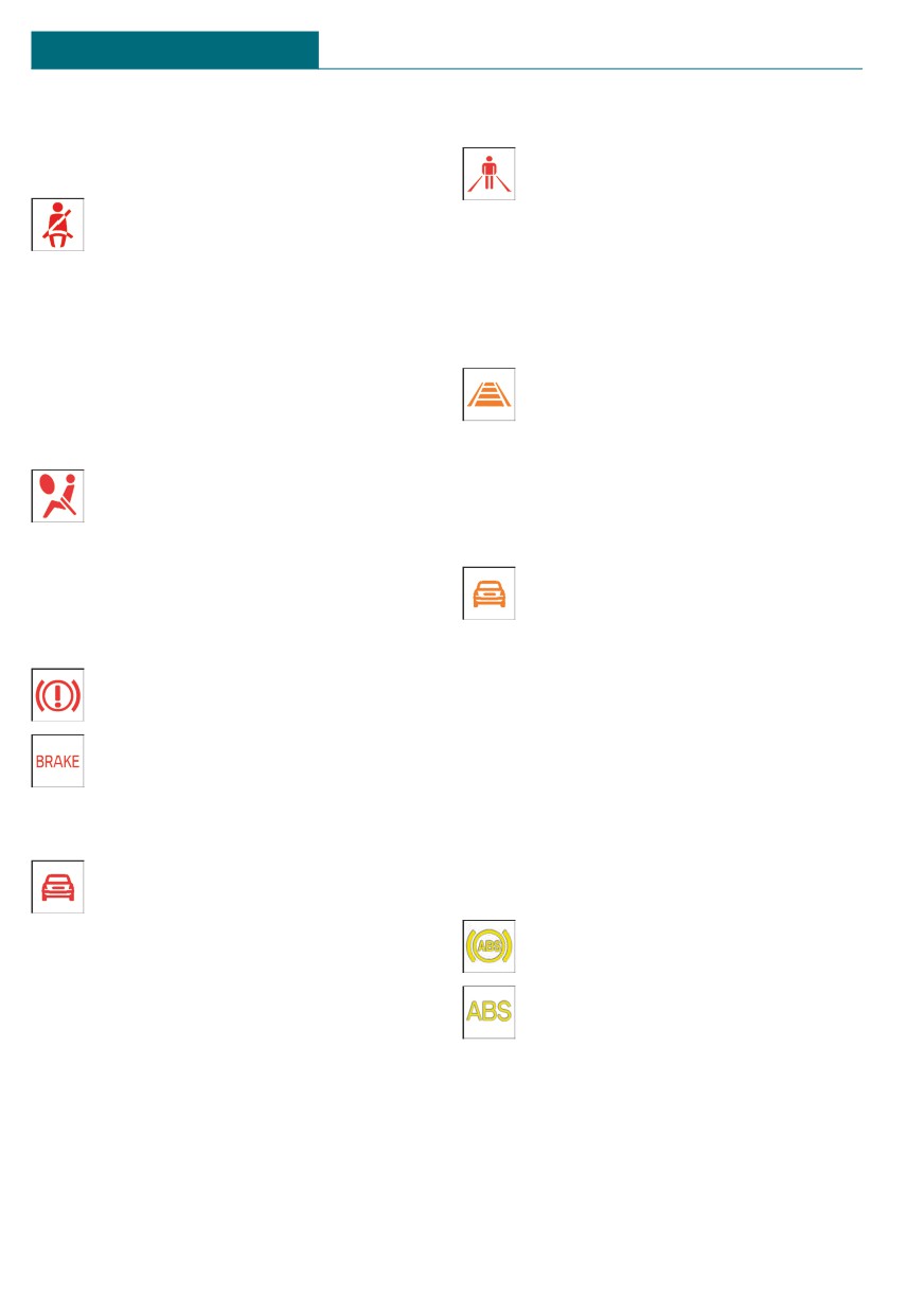
Red lights
Person warning
If a collision with a detected person
Safety belt reminder
is imminent, the symbol lights up
Indicator light flashes or is illumi-
and a signal sounds.
nated: safety belt on the driver or
passenger side is not buckled. The
Instrument cluster without enhanced
safety belt reminder can also be activated if
features: orange lights
objects are placed on the front passenger
seat.
Active Cruise Control
Make sure that the safety belts are posi-
The number bars shows the selected
tioned correctly.
distance from the vehicle driving
ahead.
Airbag system
Camera-based cruise control, refer to
Airbag system and belt tensioner
page 175.
may not be working.
Have the vehicle checked immedi-
Vehicle detection, Active Cruise Control
ately by a dealer's service center or another
Indicator light illuminates: a vehicle
qualified service center or repair shop.
has been detected ahead of you.
Indicator light flashes: the condi-
Parking brake
tions are not adequate for the system to
The parking brake is set.
work.
For releasing the parking brake, re-
The system was deactivated but applies the
fer to page 102.
brakes until the driver actively resumes
control of the vehicle by pressing on the
brake pedal or accelerator pedal.
Approach control warning
Yellow lights
Indicator light illuminates: advance
warning is issued, for example when
Antilock Braking System ABS
there is the impending danger of a
The Brake Assistant function may
collision or the distance to the vehicle
not activate. Avoid abrupt braking.
ahead is too small.
Take the longer braking distance
Increase the distance.
into account.
Indicator light flashes: acute warning of the
Have the system immediately
imminent danger of a collision when the ve-
checked by a dealer's service center
hicle approaches another vehicle at a rela-
or another qualified service center or repair
tively high differential speed.
shop.
Intervene by braking or make an evasive
maneuver.
124
Displays
CONTROLS
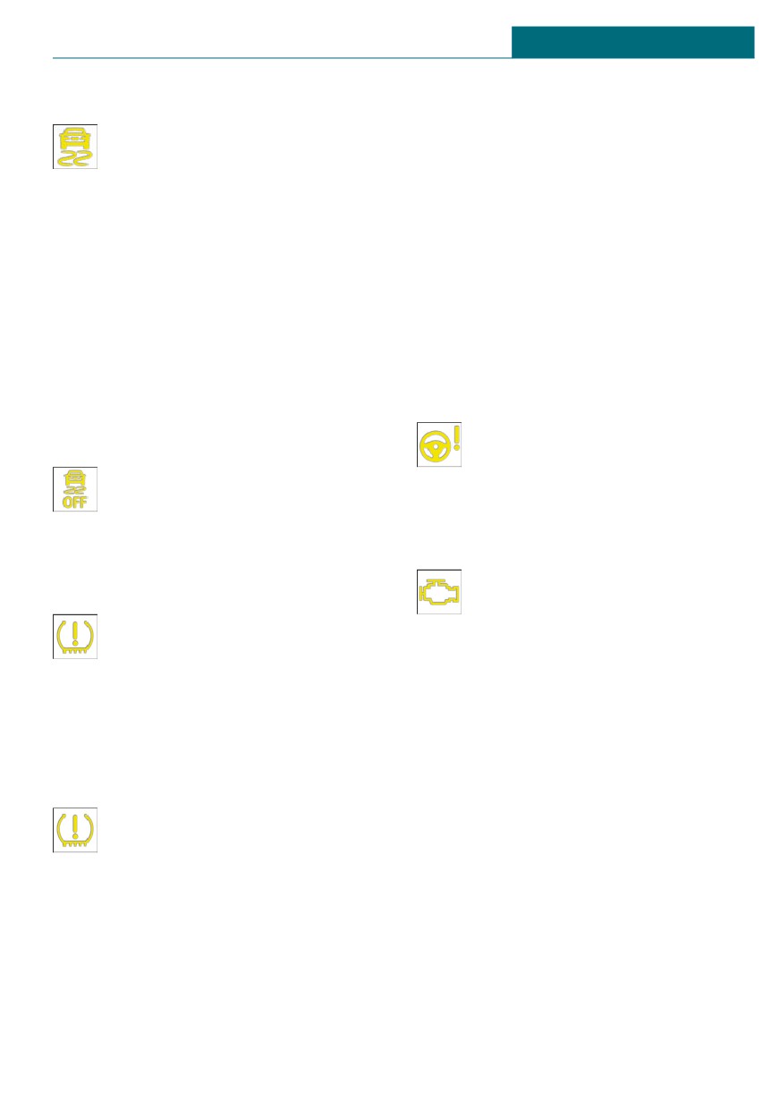
DSC Dynamic Stability Control
system automatically becomes active
again.
The indicator light flashes: DSC con-
trols the drive and braking forces.
- TPM was unable to complete the reset.
The vehicle is stabilized. Reduce
Reset the system again.
speed and modify your driving style to the
- A wheel without TPM wheel electronics
driving circumstances.
is mounted: have it checked by a deal-
The indicator light lights up: DSC has mal-
er’s service center or another qualified
functioned.
service center or repair shop as needed.
Have the system checked by a dealer's serv-
- Malfunction: have the system checked
ice center or another qualified service cen-
by a dealer’s service center or another
ter or repair shop.
qualified service center or repair shop.
DSC, refer to page 170.
Tire Pressure Monitor, refer to page 153.
DSC Dynamic Stability Control is
Steering system
deactivated or DTC Dynamic Traction
Steering system may not be working.
Control is activated
Have the system checked by a deal-
DSC is deactivated or DTC is acti-
er's service center or another quali-
vated.
fied service center or repair shop.
DSC, refer to page 170, and DTC, re-
fer to page 171.
Emissions
- The warning light lights up:
Flat Tire Monitor FTM
Emissions are deteriorating.
The FTM signals a loss of tire infla-
Have the vehicle checked as soon
tion pressure in a tire.
as possible.
Reduce your speed and stop cau-
- The warning light flashes under certain
tiously. Avoid sudden braking and steering
circumstances:
maneuvers.
This indicates that there is excessive
Flat Tire Monitor, refer to page 158.
misfiring in the engine.
Reduce the vehicle speed and have the
Tire Pressure Monitor TPM
system checked immediately; otherwise,
serious engine misfiring within a brief
The indicator light illuminates: the
period can seriously damage emission
Tire Pressure Monitor reports a low
control components, in particular the
tire inflation pressure or a flat tire.
catalytic converter.
Follow the information in the Check Control
message.
Socket for Onboard Diagnosis, refer to
The indicator light flashes and is then illu-
page 271.
minated continuously: flat tires or tire pres-
sure losses cannot be detected.
- Interference caused by systems or devi-
ces with the same radio frequency: after
leaving the area of the interference, the
125
CONTROLS
Displays
Green lights
Hiding Check Control messages
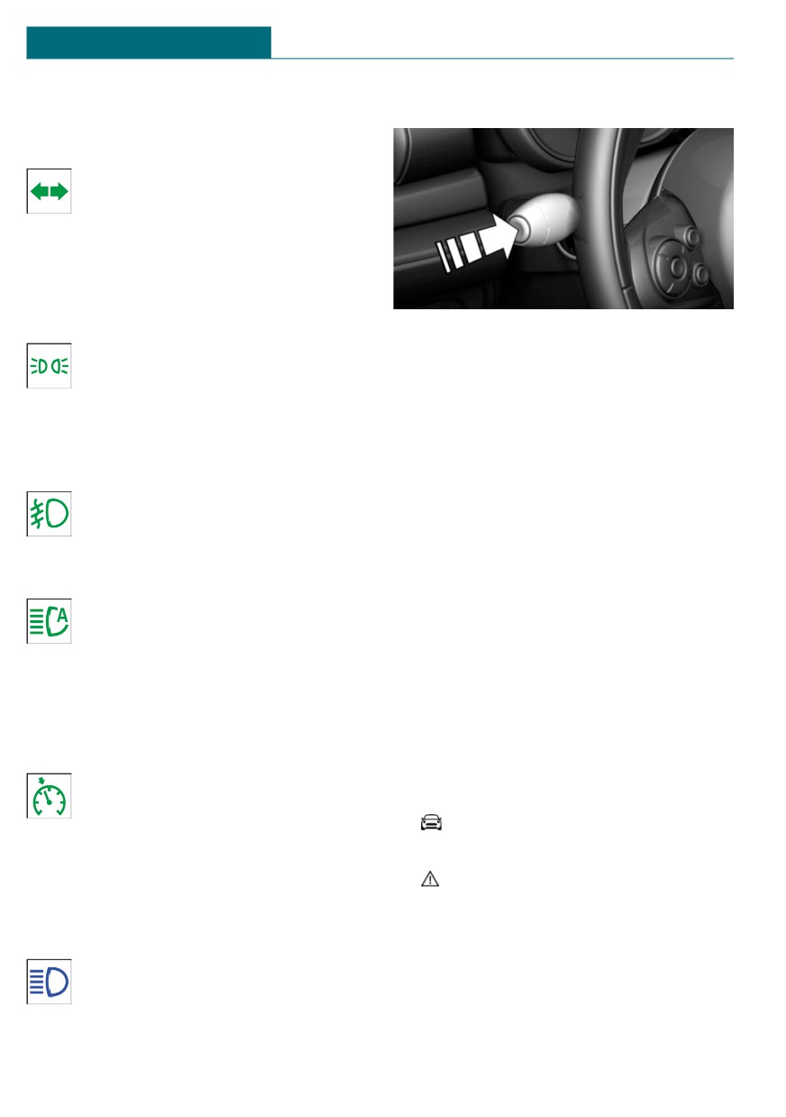
Turn signal
Turn signal switched on.
Unusually rapid flashing of the indi-
cator light indicates that a turn sig-
nal bulb has failed.
Turn signal, refer to page 102.
Parking lights, headlight
Press the button on the turn signal lever.
Parking lights or headlights are
switched on.
Continuous display
Parking lights/low beams, headlight
Some Check Control messages are displayed
control, refer to page 142.
continuously and are not cleared until the
malfunction is eliminated. If several mal-
Front fog lights
functions occur at once, the messages are
Front fog lights are switched on.
displayed consecutively.
Front fog lights, refer to page 145.
The messages can be hidden for approx.
8 seconds. After this time, they are dis-
played again automatically.
High-beam Assistant
High-beam Assistant is switched on.
Temporary display
High beams are switched on and off
Some Check Control messages are hidden
automatically depending on the traf-
automatically after approx. 20 seconds. The
fic situation.
Check Control messages are stored and can
be displayed again later.
High-beam Assistant, refer to page 144.
Displaying stored Check Control
Cruise control
messages
The system is switched on. It main-
Via the Central Information Display (CID):
tains the speed that was set using
the control elements on the steering
1.
"My MINI"
wheel.
2. "Vehicle status"
3.
"Check Control"
Blue lights
4. Select the SMS text message.
High beams
High beams are switched on.
High beams, refer to page 103.
126
Displays
CONTROLS
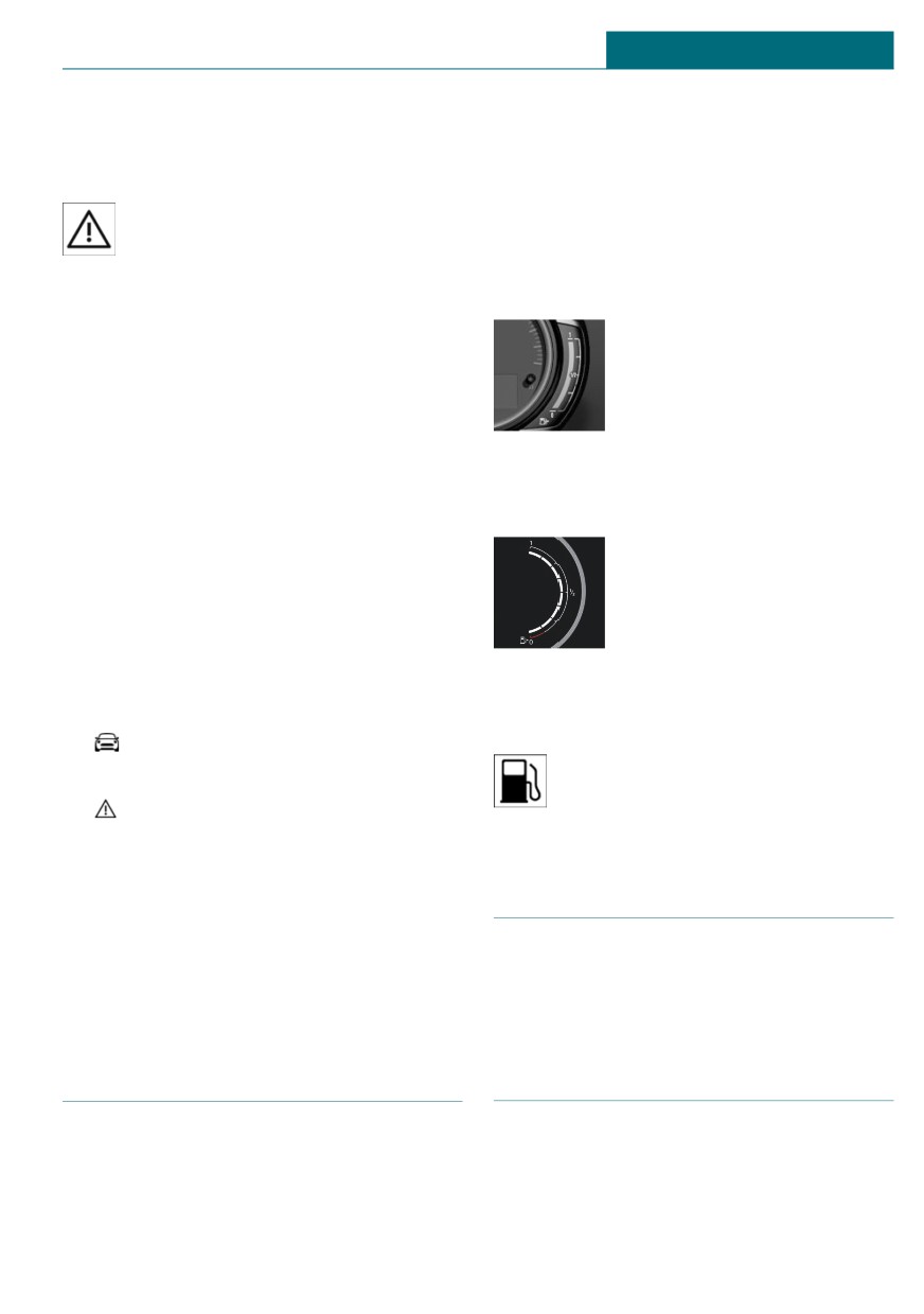
Display
General information
Vehicle tilt position may cause the display
Check Control
to vary.
At least one Check Control message
Information on refueling, refer to page 236.
is displayed or stored.
Instrument cluster without
enhanced features: display
SMS text messages
The arrow beside the fuel
SMS text messages in combination with a
pump symbol shows which
symbol in the instrument cluster explain a
side of the vehicle the fuel
Check Control message and the meaning of
filler flap is on.
the indicator/warning lights.
Supplementary SMS text messages
Instrument cluster with enhanced
Additional information, such as on the
cause of an error or the required action, can
features: display
be called up via Check Control.
The arrow beside the fuel
With urgent messages the added text will
pump symbol shows which
be automatically displayed on the Control
side of the vehicle the fuel
Display.
filler flap is on.
Depending on the Check Control message,
further help can be selected.
Via the Central Information Display (CID):
Indicator light in the instrument
cluster
1.
"My MINI"
The yellow indicator light illumi-
2. "Vehicle status"
nates, once the fuel reserve is
3.
"Check Control"
reached.
4. Select the desired text message.
5. Select the desired setting.
Tachometer
Messages after trip completion
Certain messages displayed while driving
Always avoid engine speeds in the red
are displayed again after the ignition is
warning field. In this range, the fuel supply
switched off.
is reduced to protect the engine.
Fuel gauge
Odometer and trip odometer
Concept
Concept
The current fill level of the fuel tank is dis-
The total mileage driven and the mileage
played.
driven since the last reset are displayed in
the instrument cluster.
127
CONTROLS
Displays
Instrument cluster without
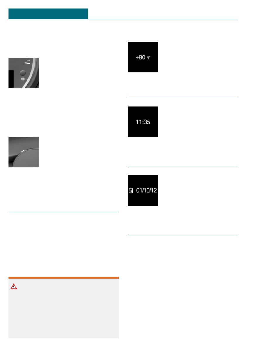
Display
additional functions: reset trip
The external temperature is
distance
displayed in the instrument
cluster.
Press the button.
- The odometer is displayed
when the ignition is
switched off.
- When the ignition is
Time
switched on, the trip od-
ometer is reset.
The time is displayed in the
instrument cluster.
Instrument cluster with enhanced
Set the time on the Central In-
features: reset trip distance
formation Display (CID), refer
Press the button.
to page 46.
- The odometer is displayed
when the ignition is
switched off.
Date
- When the ignition is
switched on, the trip od-
The date is displayed in the in-
ometer is reset.
strument cluster.
Set the date on the Central In-
formation Display (CID), refer
External temperature
to page 47.
General information
Range
If the indicator drops to +37 ℉/+3 ℃, a sig-
nal sounds.
A Check Control message is displayed.
General information
There is an increased risk of ice on roads.
When the remaining range is low:
- A Check Control message is displayed
Safety information
briefly.
- The remaining range is shown on the
Onboard Computer.
Warning
- With a dynamic driving style, for in-
Even at temperatures above +37 ℉/+3 ℃
stance fast cornering, the engine func-
there can be a risk of icy roads, for in-
tion is not always ensured.
stance on bridges or shady sections of the
road. There is a risk of accident. Modify
The Check Control message appears contin-
your driving style to the weather condi-
uously below a range of approx.
tions at low temperatures.
30 miles/50 km.
128
Displays
CONTROLS
Safety information
3. "Displays"
4. "Instrument panel"
NOTICE
5. "Current consumption"
With a driving range of less than
30 miles/50 km the engine may no longer
have sufficient fuel. Engine functions are
Service notifications
not ensured anymore. There is a risk of
damage to property. Refuel promptly.
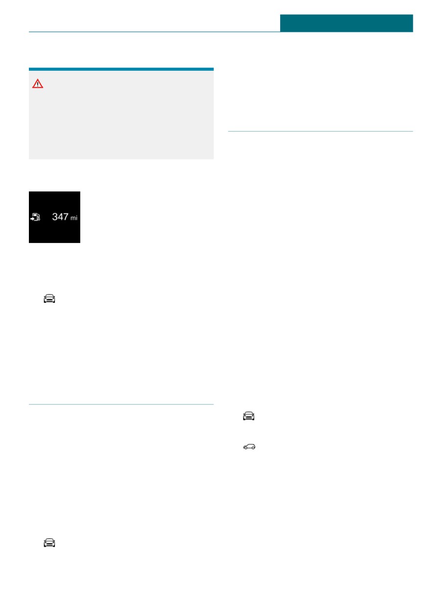
Concept
The function displays the service notifica-
Display
tions and the corresponding maintenance
scopes.
The current range is displayed
in the instrument cluster.
General information
After the ignition is switched on the instru-
ment cluster briefly displays available driv-
ing distance or time to the next scheduled
maintenance.
Displaying the cruising range
A service advisor can read out the current
Via the Central Information Display (CID):
service notifications from your vehicle key.
1.
"My MINI"
Display
2. "System settings"
3. "Displays"
Detailed information on service
4. "Instrument panel"
notifications
5. "Range"
More information on the type of service re-
quired may be displayed on the Control Dis-
play.
Current consumption
Via the Central Information Display (CID):
1.
"My MINI"
Concept
2. "Vehicle status"
Displays the current fuel consumption.
3.
"Service required"
Check whether you are currently driving in
an efficient and environmentally-friendly
Maintenance and service measures and
manner.
legally mandated inspections are dis-
played.
Displaying the current
4. Select an entry to call up detailed infor-
consumption
mation.
Via the Central Information Display (CID):
1.
"My MINI"
2. "System settings"
129
CONTROLS
Displays
Symbols
3. Move the Controller to the left.
4.
"Teleservice Call"
Symbols
Description
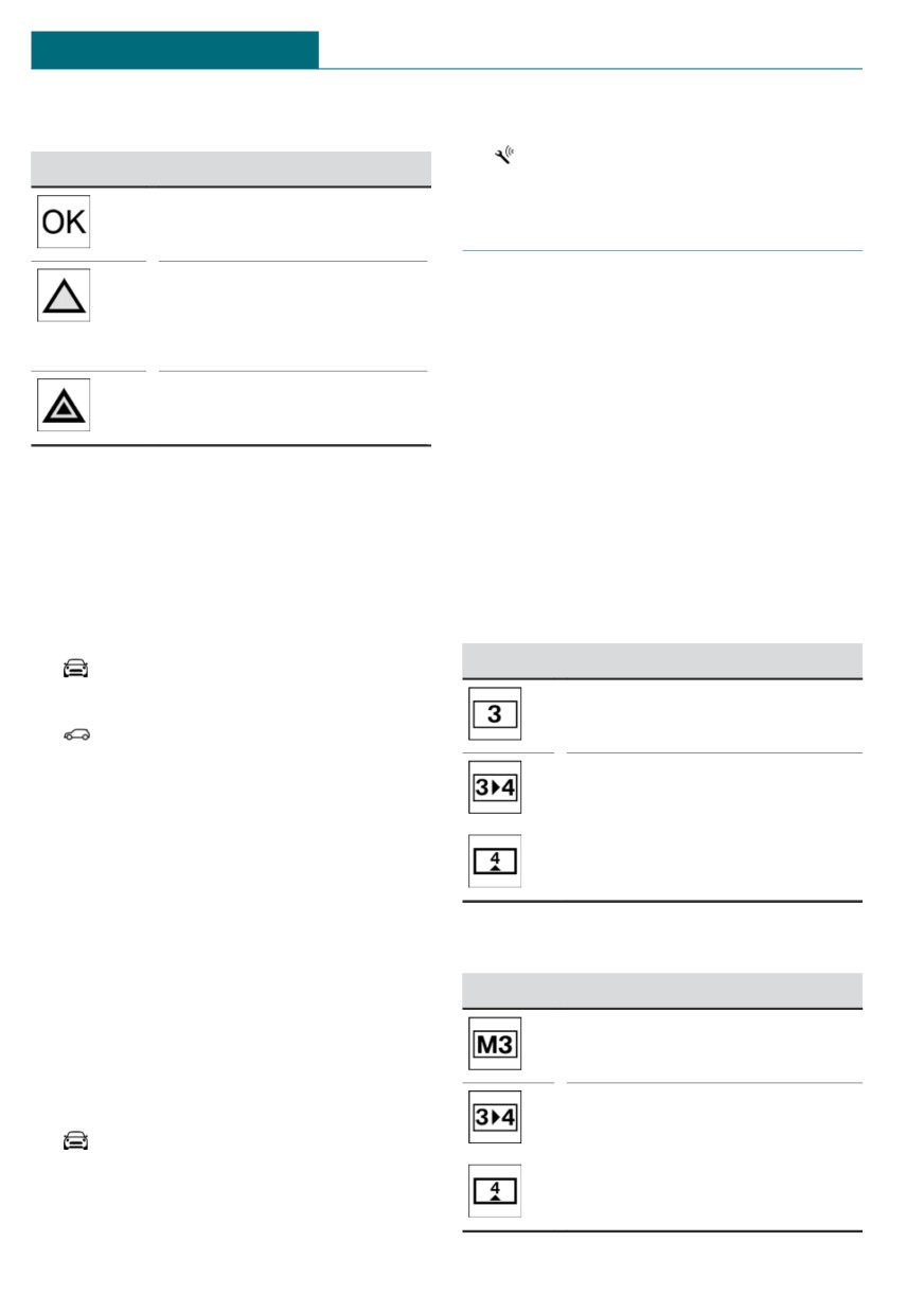
No service is currently re-
quired.
Gear shift indicator
The deadline for scheduled
Concept
maintenance or a legally
mandated inspection is ap-
The system recommends the most efficient
proaching.
gear for the current driving situation.
The service deadline has al-
General information
ready passed.
Depending on the vehicle equipment and
country version, the gear shift indicator is
active in the manual mode of the Steptronic
Entering appointment dates
transmission and with manual transmission.
Enter the dates for the mandatory vehicle
Suggestions to shift up or down are dis-
inspections.
played in the instrument cluster.
Make sure that the vehicle's date and time
are set correctly.
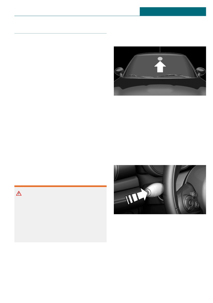
Manual transmission: displaying
Via the Central Information Display (CID):
Example Description
1.
"My MINI"
2. "Vehicle status"
Efficient gear is set.
3.
"Service required"
4. "Vehicle inspection"
Depending on the equipment
5. "Date:"
version, shift to a more effi-
cient gear.
6. Select the desired setting.
Automatic Service Request
Data regarding the service status or legally
mandated vehicle inspections is automati-
Steptronic transmission: displaying
cally transmitted to your dealer’s service
center before your vehicle is due for serv-
Example Description
ice.
Efficient gear is set.
You can check when your dealer’s service
center was notified.
Via the Central Information Display (CID):
Depending on the equipment
version, shift to a more effi-
1.
"My MINI"
cient gear.
2. "Vehicle status"
130
Displays
CONTROLS
Speed Limit Info
Overview
Camera
Speed Limit Info
Concept
Speed Limit Info shows the current maxi-
mum permitted speed in the instrument
cluster.
General information
The camera at the base of the interior mir-
ror detects traffic signs at the edge of the
The camera is installed near the interior
road as well as overhead sign posts. Traffic
mirror.
signs with extra symbols for wet road con-
ditions, etc., are also detected and compared
Keep the windshield in front of the interior
with the vehicle's onboard data, such as
mirror clean and clear.
from the rain sensor, and will be displayed
depending on the situation.
Display
With the navigation system, the system
Depending on the vehicle equipment, Speed
takes into account the information stored in
Limit Info is displayed permanently in the
the navigation data and also displays speed
instrument cluster or via the Onboard Com-
limits present on routes without signs.
puter.
Speed limits when towing a trailer are not
shown.
Safety information
Warning
The system cannot serve as a substitute
for the driver’s personal judgment in as-
sessing visibility and traffic situation.
There is a risk of accident. Adjust driving
Press button on the turn signal lever several
style to traffic conditions. Watch traffic
times, if needed.
closely and actively intervene where ap-
propriate.
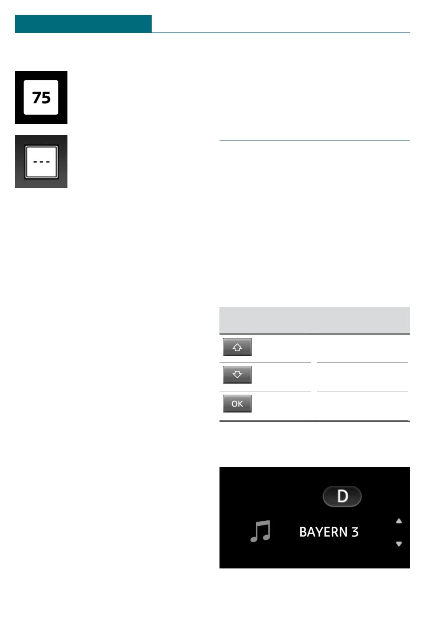
Speed Limit Info is displayed in the instru-
ment cluster.
131
CONTROLS
Displays
Speed Limit Info
- When traffic signs that are valid for a
parallel road are detected.
The last speed limit detected.
- During calibration of the camera imme-
diately after vehicle delivery.
Selection lists
With navigation system:
Speed Limit Info is not availa-
ble.
General information
Depending on the vehicle equipment, the
buttons on the steering wheel and the dis-
play in the instrument cluster can be used
Speed Limit Info can also be displayed in
to display or use the following:
the Head-up Display.
- Current audio source.
System limits
- Phone redial.
The system may not be fully functional and
- Turn on voice activation system.
may provide incorrect information in the
following situations:
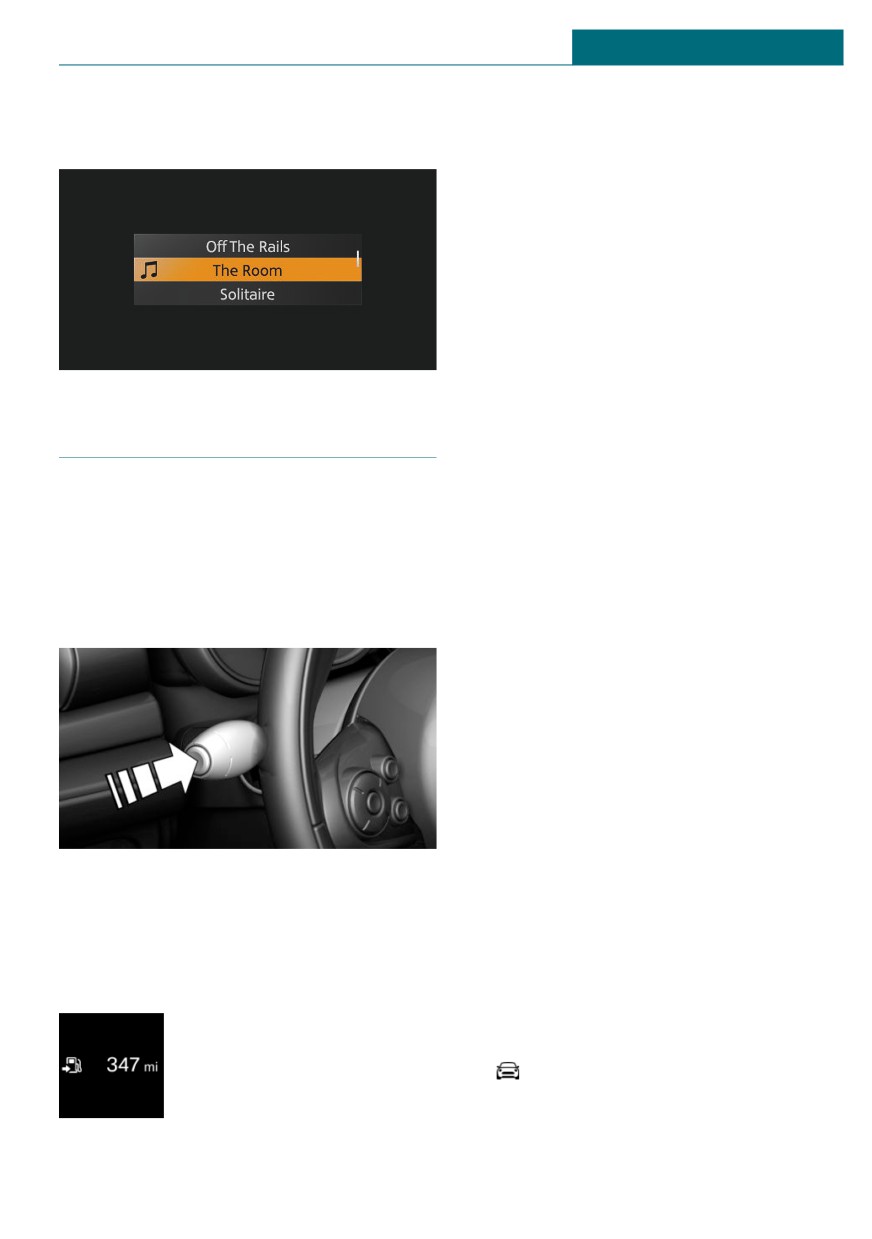
Activating a list and adjusting the
-
In heavy fog, wet conditions, or snow-
setting
fall.
-
When traffic signs are fully or partially
Button on the
Function
concealed by objects, stickers or paint.
steering wheel
-
When driving very close to the vehicle
Move selection up.
in front of you.
-
When driving toward bright lights or
Move selection
strong reflections.
down.
-
When the windshield in front of the in-
Confirm the selec-
terior mirror is fogged over, dirty or cov-
tion.
ered by a sticker, etc.
-
In the event of incorrect detection by
Instrument cluster without
the camera.
enhanced features: display
-
If the speed limits stored in the naviga-
tion system are incorrect.
-
In areas not covered by the navigation
system.
-
When roads differ from the navigation,
such as due to changes in road routing.
-
When passing buses or trucks with a
speed sticker.
-
If the traffic signs are non-conforming.
132
Displays
CONTROLS
Instrument cluster with enhanced
–
GREEN Info.
features: display
When GREEN Mode is activated.
-
Average consumption, fuel.
–
Average consumption since delivery
from the factory.
-
Current consumption, fuel.
–
Average speed.
–
Date.
–
Engine temperature display.
–
Always Open Timer.
–
With equipment version with Head-up
Display and navigation:
Onboard Computer
Distance to destination.
When destination guidance is activated
Concept
in the navigation system.
The Onboard Computer displays different
-
With equipment version with Head-up
vehicle data in the instrument cluster, such
Display and navigation:
as average values.
Time of arrival.
When destination guidance is activated
Calling up information
in the navigation system.
-
Instrument cluster without enhanced
features:
Speed Limit Info.
-
Vehicle speed.
–
Trip odometer.
The unit of some information can be
changed.
Setting units, refer to page 47.
Press the button on the turn signal lever.
Information is displayed in the instrument
Selecting information
cluster.
Depending on the vehicle equipment, you
can select what information from the On-
board Computer can be accessed in the in-
Information at a glance
strument cluster.
Repeatedly pressing the but-
Via the Central Information Display (CID):
ton on the turn signal lever
calls up the following informa-
1.
"My MINI"
tion:
2. "System settings"
3. "Displays"
- Range.
133
CONTROLS
Displays
4. "Instrument panel"
Engine temperature display
5. Select the desired setting.
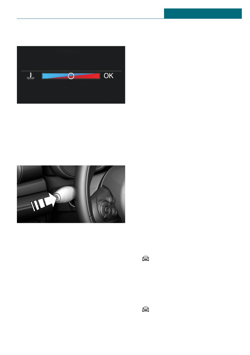
Concept
Settings are stored for the profile currently
The current engine temperature, based on a
used.
combination of coolant and engine oil tem-
perature is displayed. As soon as the opti-
Information in detail
mum operating temperature has been at-
tained, the indicator is in the center
Range
position.
Displays the estimated cruising range avail-
able with the remaining fuel.
General information
The range is calculated based on your driv-
If the engine oil or coolant, and thus the en-
ing style over the last 20 miles/30 km.
gine, become too hot, a Check Control mes-
sage is displayed too.
GREEN info
When the engine temperature is too
The achieved range extension may be dis-
high, a red indicator light is dis-
played as a bonus range.
played.
Average consumption
When the engine oil temperature is
too high, a red indicator light is dis-
The average consumption is calculated for
played.
the period while the engine is running.
The average consumption is calculated for
To check the coolant level, refer to
the distance traveled since the last reset by
page 268.
the Onboard Computer.
Instrument cluster without enhanced
Average speed
features: display
Periods in which the vehicle is parked with
the engine manually stopped are not in-
cluded in the calculation of the average
speed.
Resetting average values
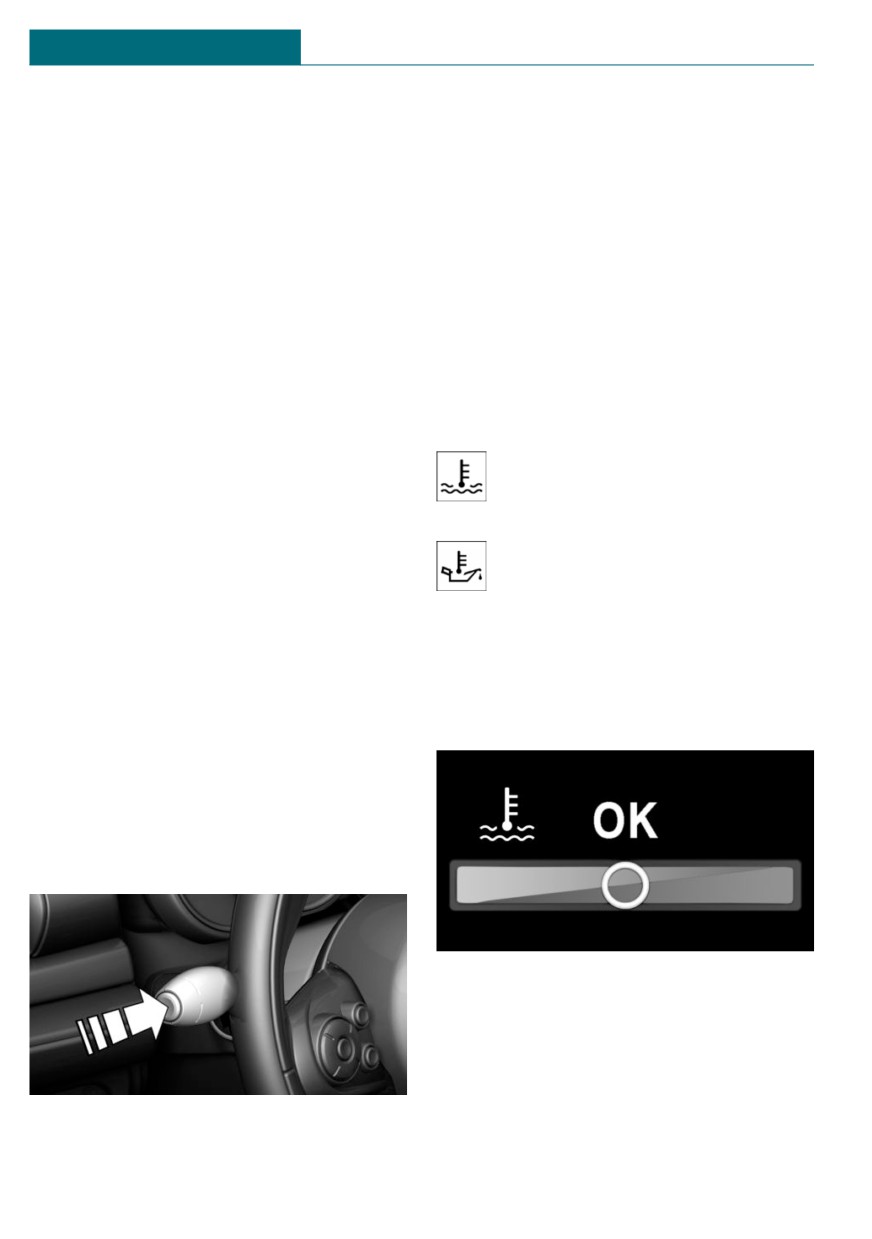
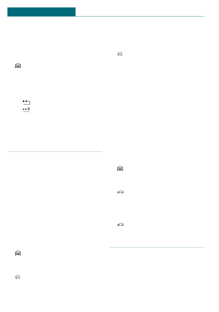
Press and hold the button on the turn signal
lever.
134
Displays
CONTROLS
Instrument cluster with enhanced
destination is entered in the navigation sys-
features: display
tem before the trip is started.
The time must be correctly set.
Instrument cluster without additional
functions: Speed Limit Info
Speed Limit Info shows the current maxi-
mum permitted speed in the instrument
cluster.
Onboard Computer on the Control
Display
Always Open Timer
The Always Open Timer displays the cur-
Concept
rent driving time and total driving time
The Onboard Computer displays different
with the convertible top open in minutes
vehicle data on the Control Display, such as
and hours.
average values.
Reset the Always Open Timer
General information
Two types of Onboard Computers are availa-
ble on the Control Display:
- "Onboard info": average values, such as
the consumption, are displayed. The val-
ues can be reset individually.
- "Trip computer": the values deliver an
overview of a specific route and can be
reset as often as necessary.
Reset the current driving time: press button
Calling up the Onboard Computer or
on the turn signal lever for approx. 2 sec-
trip computer
onds with the driving times displayed.
Via the Central Information Display (CID):
1.
"My MINI"
Distance to destination
Depending on the vehicle equipment, the
2. "Driving information"
distance remaining to the destination is dis-
3. "Onboard info" or "Trip computer"
played if a destination is entered in the nav-
igation system before the trip is started.
Resetting the Onboard Computer
The distance to the destination is adopted
Via the Central Information Display (CID):
automatically.
1.
"My MINI"
Time of arrival
2. "Driving information"
Depending on the vehicle equipment, the
3. "Onboard info"
estimated time of arrival is displayed if a
135
CONTROLS
Displays
4. "Consumption" or "Speed"
Via MINI Driving Modes switch:
5. "OK"
1. Activate SPORT.
2. "Sport displays"
Resetting the trip computer
3.
"Sports instruments"
Via the Central Information Display (CID):
1.
"My MINI"
Vehicle state
2. "Driving information"
General information
3. "Trip computer"
The following vehicle and surrounding area
4. Move the Controller to the left, if
data is automatically checked and evaluated
needed.
in succession:
-
"Reset": all values are reset.
- Range.
–
"Automatic reset": all values are
- Engine temperature.
reset approx. 4 hours after the vehi-
- External temperature.
cle has come to a standstill.
- SPORT program state.
5. If necessary, "OK"
Finally, a total evaluation of the vehicle
state is displayed.
Driving Excitement
Checking vehicle state
Via the Central Information Display (CID):
Concept
On the Control Display, sport instruments
1.
"My MINI"
can be displayed, and the vehicle state can
2. "Technology in action"
be checked before the use of the SPORT
3. "Sport displays"
program.
4.
"Vehicle and surroundings"
Sport instruments
Via the MINI Driving Modes switch:
1. Activate SPORT.
General information
2. "Sport displays"
On the Control Display, values for power
and torque are displayed.
3.
"Vehicle and surroundings"
Displaying sport instruments
Via the Central Information Display (CID):
Speed warning
1.
"My MINI"
Concept
2. "Technology in action"
A speed limit can be set that when reached
3. "Sport displays"
will cause a warning to be issued.
4.
"Sports instruments"
136
Displays
CONTROLS
General information
Basic displays
The warning is repeated if the vehicle speed
Basic functions, for instance the tachome-
exceeds the set speed limit again, after it
ter, can be set to be displayed continually if
has dropped below it by 3 mph/5 km/h.
so desired.
Adjusting
Event displays
Via the Central Information Display (CID):
Functions that are only displayed tempora-
rily, for instance the volume or temperature
1.
"My MINI"
settings, can be set as event displays.
2. "Vehicle settings"
Several vehicle assistance functions can
also be displayed on the LED ring. This dis-
3. "Speed warning"
play corresponds with the displays of the
4. "Warning at:"
function in the respective display.
5. Turn the Controller until the desired
speed is displayed.
Example: tachometer
6. Press the Controller.
Like the tachometer in the instrument clus-
ter, the light animations of the tachometer's
Activating/deactivating
basic display show the current RPMs and
the respective RPM warning thresholds.
Via the Central Information Display (CID):
1.
"My MINI"
Display
2. "Vehicle settings"
3. "Speed warning"
4. "Speed warning"
Setting your current speed as the
speed warning
Via the Central Information Display (CID):
1.
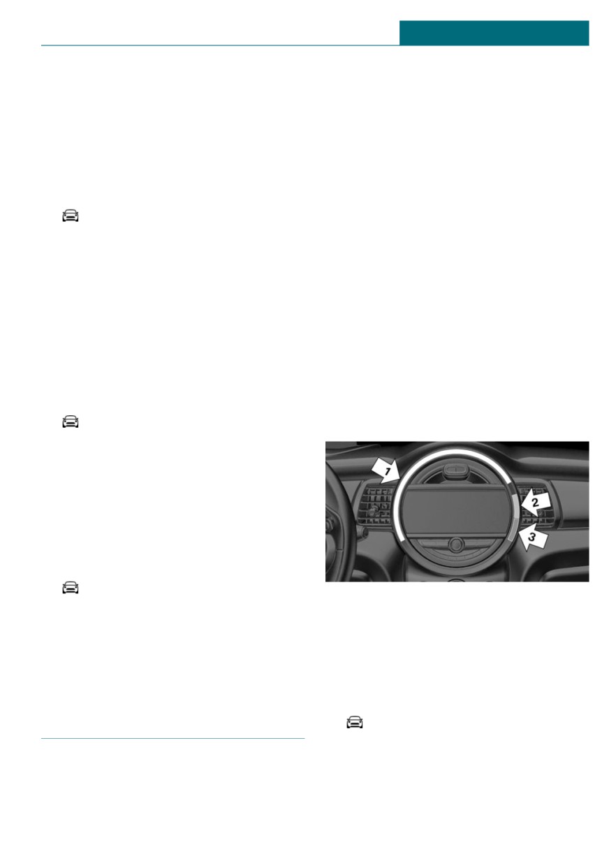
"My MINI"
- Arrow 1: current RPM.
2. "Vehicle settings"
- Arrow 2: prewarning field.
3. "Speed warning"
- Arrow 3: warning field.
4. "Select current speed"
Switching on/off LED ring
Via the Central Information Display (CID):
LED ring on the central in-
1.
"My MINI"
strument cluster
2. "System settings"
Concept
3. "Displays"
The LED ring displays light animations to
4. "Center Instrument"
represent specific functions.
5. "Center Instrument"
137
CONTROLS
Displays
Adjusting the LED ring
Safety information
Via the Central Information Display (CID):
Warning
1.
"My MINI"
When extending and retracting the projec-
2. "System settings"
tion screen of the Head-up Display, body
3. "Displays"
parts can be jammed. There is a risk of in-
4. "Center Instrument"
jury. Make sure that the area of movement
of the projection screen is clear during
5. "Basic display" or "Event display"
opening and closing.
6. Select the desired setting.
Setting the brightness
NOTICE
The brightness can be adjusted when night
The Head-up Display consists of sensitive
lighting is active in the instrument cluster.
components that can easily be scraped or
Via the Central Information Display (CID):
damaged. There is a risk of damage to
property. Do not place any objects on the
1.
"My MINI"
Head-up Display, attach to system compo-
2. "System settings"
nents or plug into the system. Do not
move the moving parts manually.
3. "Displays"
4. "Center Instrument"
5. "Brightness at night"
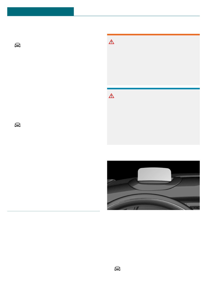
Overview
6. Turn the Controller until the desired
brightness is set.
7. Press the Controller.
The setting is stored for the driver profile
currently used.
Head-up Display
Concept
Switching the Head-up Display
This system projects important information
on/off
into the driver's field of vision, for instance
When switching on, the projection lens of
the speed.
the Head-up Display is extended. When
The driver can get information without
switching off, the projection lens of the
averting his or her eyes from the road.
Head-up Display is retracted again.
Via the Central Information Display (CID):
General information
1.
"My MINI"
Follow the instructions for cleaning the
2. "System settings"
Head-up Display. For additional informa-
tion, see the chapter on care.
138

Displays
CONTROLS
3. "Displays"
3. "Displays"
4. "Head-Up Display"
4. "Head-Up Display"
5. "Head-Up Display"
5. "Brightness"
6. Turn the Controller until the desired
Display
brightness is set.
7. Press the Controller.
Overview
When the low beams are switched on, the
The following information is displayed on
brightness of the Head-up Display can be
the Head-up Display:
additionally influenced using the instru-
- Vehicle speed.
ment lighting, refer to page 146.
- Navigation instructions.
The setting is stored for the driver profile
- Check Control messages.
currently used.
- Selection list from the instrument clus-
Adjusting the height
ter.
Via the Central Information Display (CID):
- Driver assistance systems.
Some of this information is only displayed
1.
"My MINI"
briefly as needed.
2. "System settings"
3. "Displays"
Selecting displays in the Head-up
Display
4. "Head-Up Display"
Via the Central Information Display (CID):
5. "Height"
6. Turn the Controller until the desired
1.
"My MINI"
height is reached.
2. "System settings"
7. Press the Controller.
3. "Displays"
The setting is stored for the driver profile
4. "Head-Up Display"
currently used.
5. "Displayed information"
Setting the rotation
6. Select the desired displays in the Head-
up Display.
The screen of the Head-up Display can be
rotated around its own axis.
Settings are stored for the driver profile
currently used.
Via the Central Information Display (CID):
1.
"My MINI"
Setting the brightness
2. "System settings"
The brightness is automatically adjusted to
the ambient brightness.
3. "Displays"
The basic setting can be adjusted manually.
4. "Head-Up Display"
Via the Central Information Display (CID):
5. "Rotation"
1.
"My MINI"
2. "System settings"
139
CONTROLS
Displays
6. Turn the Controller until the desired set-
Display
ting is selected.
7. Press the Controller.
The setting is stored for the driver profile
currently used.
Display visibility
The visibility of the displays in the Head-up
Display is influenced by the following fac-
tors:
- Certain sitting positions.
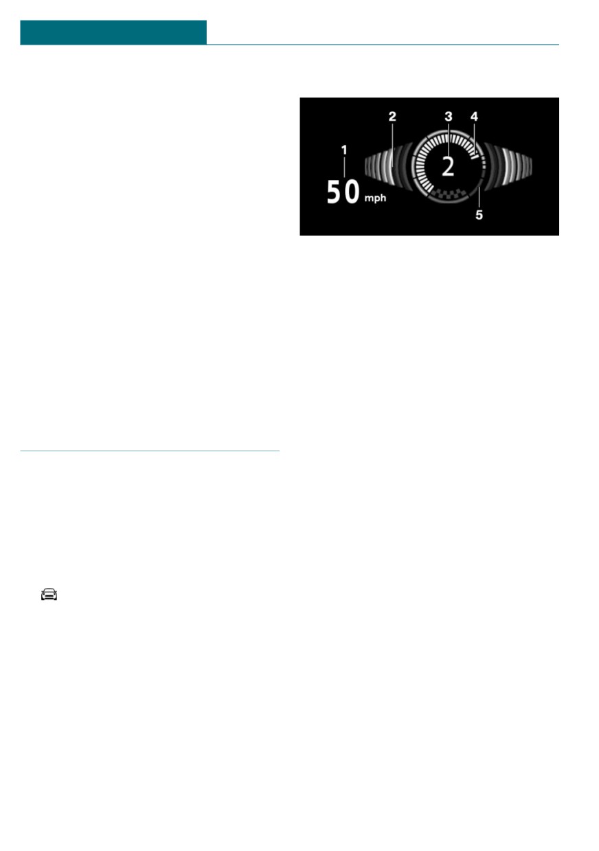
1
Vehicle speed
- Objects on the cover of the Head-up Dis-
2
Shift point indicator
play.
3
Gear display
- Sunglasses with certain polarization fil-
4
Current engine speed
ters.
5
Warning field, speed
- Wet roads.
- Unfavorable light conditions.
Shift point indicator
Concept
John Cooper Works: sport dis-
The shift point indicator in the Head-up
plays in the Head-up Display
Display indicates the optimum shifting
point. Thus, with a sporty driving style, the
General information
best possible vehicle acceleration is ach-
ieved.
The sport displays in the Head-up Display
assist with a sporty driving style.
Functional requirements
- Steptronic Sport transmission:
Switching on
Manual mode M/S and, if necessary, Dy-
Via the Central Information Display (CID):
namic Traction Control DTC are acti-
1.
"My MINI"
vated.
2. "System settings"
- Press the accelerator pedal all the way
down.
3. "Displays"
4. "Head-Up Display"
Display
5. "Displayed information"
Successive gray illuminated fields indicate
6. "Sport displays"
the upcoming shift moment.
With navigation system: if the sport dis-
Shift up immediately when the red fields
plays are switched on, no navigation con-
light up.
tent will be displayed on the Head-up Dis-
When the maximum speed is reached, the
play.
entire display flashes red and the supply of
140
Displays
CONTROLS
fuel is interrupted in order to protect the
To reset the total driving time, contact your
engine.
service center.
Always Open Timer
Vehicle status
Concept
General information
The Always Open Timer displays the driving
The status can be displayed and actions per-
times with open convertible top on the Con-
formed for several systems.
trol Display and in the Onboard Computer.
Opening the vehicle status
General information
Via the Central Information Display (CID):
Depending on the vehicle equipment, the
1.
"My MINI"
Always Open Timer can also be displayed as
a light animation on the LED ring of the
2. "Vehicle status"
central instrument cluster.
Information at a glance
Displaying the Always Open Timer
Symbols
Description
1.
"My MINI"
2. "Openometer"
"Flat Tire Monitor": status of
the run-flat tires, refer to
page 158.
Display
The following information is displayed on
"Tire Pressure Monitor": sta-
the Control Display:
tus of the Tire Pressure
Monitor TPM, refer to
- Current driving time with the
page 153.
convertible top open in minutes and
hours.
"Engine oil level": Electronic
- Total driving time with the convertible
engine oil level check, refer
top open in minutes and hours.
to page 264.
- Current external temperature while driv-
"Check Control": Check Con-
ing with the convertible top open.
trol messages are stored in
Maximum 99 hours and 59 minutes are dis-
the background and can be
played for the current driving time, and
displayed on the Control
maximum 999 hours and 59 minutes for the
Display. Displaying stored
total driving time.
Check Control messages, re-
fer to page 126.
Reset the current driving time
"Service required": display-
1.
"My MINI"
ing service notifications, re-
fer to page 129.
2. "Openometer"
"Teleservice Call": Serv-
3. "Reset trip"
ice Request.
141