Dodge Journey (2020 year). Manual in english - page 6
 

  Index      Manuals     Dodge Journey (2020 year). Manual in english


Search            copyright infringement  


Content      ..     4      5      6      7     ..


Dodge Journey (2020 year). Manual in english - page 6


88

GETTING TO KNOW YOUR VEHICLE


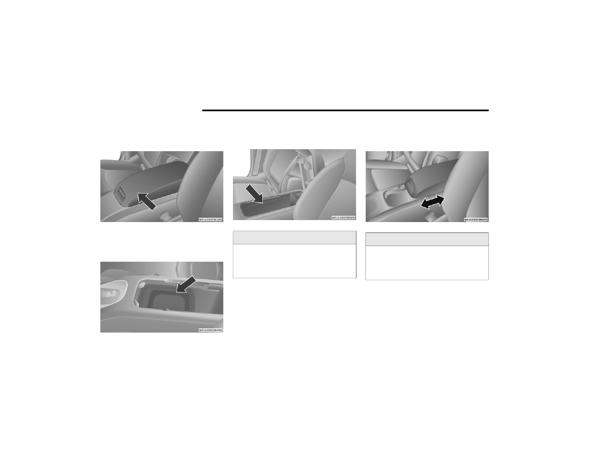
Center Console Storage

There is a storage tray and storage compart-

ment located under the center console armrest.

Center Console

Pull upward on the release handle, located on 

the front of the lid, to gain access to the storage 

tray and storage compartment.

Center Console Storage Tray

The storage tray can be slid forward and rear-

ward or removed to access the center console 

storage compartment.

Center Console Storage Compartment

Sliding Armrest

The center console armrest can also slide rear-

ward for easy access to the storage area.

Sliding Armrest

WARNING!

Do not operate this vehicle with a console 

compartment lid in the open position. Driving 

with the console compartment lid open may 

result in injury in a collision.

WARNING!

Do not operate this vehicle with a console 

compartment lid in the open position. Driving 

with the console compartment lid open may 

result in injury in a collision.

GETTING TO KNOW YOUR VEHICLE

89

Cupholders   

There are two cupholders, located in the center 

floor console, for the front passengers.

Floor Console Cupholders

For passengers in the second row, there are two 

cupholders located in the center armrest 

between the two seats.
When the armrest is folded flat, the cupholders 

are in the back of the Head Restraint. The Head 

Restraint can be adjusted to better position the 

cupholders.

Armrest Cupholders

For vehicles equipped with third row seating, 

there are additional cupholders located in the 

trim panels.
In addition to cupholders, your vehicle may also 

be equipped with bottle holders. The bottle 

holders are located on the door trim panels.

Door Bottle Holder

Power Outlets  

A 12 Volt (13 Amp) power outlet is located in the 

center console below the radio. The power 

outlet has power available when the ignition in 

the ACC or ON/RUN position.

Front 12 Volt Power Outlet

WARNING!

If containers of hot liquid are placed in the 

bottle holder, they can spill when the door is 

closed, burning the occupants. Be careful 

when closing the doors to avoid injury.

2

90

GETTING TO KNOW YOUR VEHICLE


This power outlet will also operate a conven-

tional cigar lighter unit. To preserve the heating 

element, do not hold the lighter in the heating 

position.
A second 12 Volt (13 Amp) power outlet is 

located inside the center console storage area. 

Power is available with the ignition is in the OFF, 

ACC, or ON/RUN position.

Center Console 12 Volt Power Outlet

A third fused 12 Volt power outlet is located on 

the back of the center console. This power 

outlet has power available when the ignition is 

in the OFF, ACC, or ON/RUN position.

Rear Seat 12 Volt Power Outlet

A fourth fused 12 Volt power outlet is located on 

the left quarter trim panel in the cargo area. 

This power outlet has power available when the 

ignition is in the ACC or ON/RUN position.

Rear Cargo Area Power Outlet

CAUTION!

Do not exceed the maximum power of 

160 Watts (13 Amps) at 12 Volts. If the

160 Watt (13 Amp) power rating is 

exceeded the fuse protecting the system 

will need to be replaced.

The power outlet on the bottom of the 

center console shares the fuse with the 

power outlet on the back of the console. 

The combined usage must not exceed

160 Watts (13 Amps) at 12 Volts.

Power outlets are designed for accessory 

plugs only. Do not insert any other object in 

the power outlets as this will damage the 

outlet and blow the fuse. Improper use of 

the power outlet can cause damage not 

covered by your New Vehicle Limited 

Warranty.

GETTING TO KNOW YOUR VEHICLE

91

(Continued)

(Continued)

Power Outlet Fuses

Power Inverter — If Equipped 

Your vehicle may be equipped with a 115 Volt 

AC (150 Watt maximum) power outlet located 

on the back of the center console. This outlet 

can power mobile phones, electronics and other 

low power devices requiring power up to 

150 Watts. Certain high-end video game 

consoles will exceed this power limit, as will 

most power tools.

Power Inverter

1 — F103 20 Amp Yellow — Power Outlet Console 

Bin And Power Outlet Console Rear
2 — F102 20 Amp Yellow — Cigar Lighter Instru-

ment Panel And Power Outlet Left Rear Cargo 

Area

WARNING!

To avoid serious injury or death:

Only devices designed for use in this type of 

outlet should be inserted into any 12 Volt 

outlet.

Do not touch with wet hands.

Close the lid when not in use and while 

driving the vehicle.

If this outlet is mishandled, it may cause an 

electric shock and failure.

CAUTION!

Many accessories that can be plugged in 

draw power from the vehicle's battery, even 

when not in use (i.e., cellular phones, etc.). 

Eventually, if plugged in long enough, the 

vehicle's battery will discharge sufficiently 

to degrade battery life and/or prevent the 

engine from starting.

Accessories that draw higher power (i.e., 

coolers, vacuum cleaners, lights, etc.) will 

degrade the battery even more quickly. 

Only use these intermittently and with 

greater caution.

After the use of high power draw accesso-

ries, or long periods of the vehicle not being 

started (with accessories still plugged in), 

the vehicle must be driven a sufficient 

length of time to allow the alternator to 

recharge the vehicle's battery.

WARNING!

 (Continued)

Power outlets are designed for accessory 

plugs only. Do not hang any type of acces-

sory or accessory bracket from the plug.

CAUTION!

 (Continued)

2

92

GETTING TO KNOW YOUR VEHICLE


(Continued)

The power inverter is designed with built-in over-

load protection. If the power rating of 150 Watts 

is exceeded, the power inverter will automati-

cally shut down. Once the electrical device has 

been removed from the outlet the inverter 

should automatically reset. If the power rating 

exceeds approximately 170 Watts, the power 

inverter may have to be reset manually. To reset 

the inverter manually press the power inverter 

button off and on within the Uconnect Settings. 

To avoid overloading the circuit, check the 

power ratings on electrical devices prior to 

using the inverter.

NOTE:

Due to built-in overload protection, the power 

outlet will shut down if the 115 Volt AC

(150 Watt maximum) power rating is exceeded.

Power Inverter Operation

The power inverter is turned on and off using 

the Uconnect System.

Vehicles Equipped With Radio 4.3
To turn the power inverter on or off perform the 

following:

1. Press the “More” button on the faceplate 

(located next to the Uconnect display).

2. Press the “Outlet” button on the touch-

screen (located on the Uconnect display) to 

turn the power inverter on or off.

Vehicles Equipped With Uconnect 3/3 NAV
To turn the power inverter on or off perform the 

following:

1. Press the “Controls” button on the 

touchscreen.

2. Press the “Outlet” button on the touch-

screen to turn the power inverter on or off.

Sunglasses Storage 

To access the storage compartment, push on 

the raised bars on the compartment door in the 

center of the console and release and the door 

will swing downward.

Sunglasses Storage Compartment

WARNING!

To avoid serious injury or death:

Do not use a three-prong adaptor.

Do not insert any objects into the 

receptacles.

Do not touch with wet hands.

Close the lid when not in use.

If this outlet is mishandled, it may cause an 

electric shock and failure.

WARNING!

 (Continued)

GETTING TO KNOW YOUR VEHICLE

93

ROOF LUGGAGE RACK — IF EQUIPPED   

The roof rack cross rails and side rails are 

designed to carry cargo weight. The load must 

not exceed 150 lbs (68 kg), and it should be 

distributed uniformly over the cross rails. In 

addition, the roof rack does not increase the 

total load carrying capacity of the vehicle. Be 

sure the total load of cargo inside the vehicle 

plus that on the roof rack does not exceed the 

maximum vehicle load capacity.

NOTE:

The roof rack side rails on your vehicle are NOT 

designed to carry a load without the addition of 

crossbars. 

Metal crossbars are offered by Mopar accesso-

ries to provide a functional roof rack system. 

See an authorized dealer.

To Move The Crossbars

1. Loosen the knobs on top of each crossbar 

approximately six turns to disengage the 

clamp tooth from the side rail.

Crossbar Knobs

2. Relocate the crossbars, aligning the 

crossbar stanchions (end pieces) with one 

of the vertical marks on the outboard 

surface of the side rail for proper posi-

tioning. There are four frontward marks for 

the front crossbar and four rearward marks 

for the rear crossbar. Make sure the cross-

bars remain equally spaced or parallel at 

any position for proper function.

3. Tighten the knobs on each crossbar to lock 

it in position. As you tighten the knob, make 

sure the clamp tooth engages completely 

into the side rail slot.

4. Attempt to move the crossbar to ensure that 

it is locked in position.

NOTE:

To help control wind noise when installing the 

crossbars, make sure the arrows marked on 

the underside of the crossbars face the front 

of the vehicle.

To help reduce the amount of wind noise 

when the crossbars are not in use, fasten the 

front crossbar in the fourth position from the 

front and the rear crossbar in the eighth posi-

tion. The tie down holes on the crossbar ends 

should always be used to tie down the load. 

Check the straps frequently to be sure that 

the load remains securely attached.

2

94

GETTING TO KNOW YOUR VEHICLE


(Continued)

(Continued)

WARNING!

Cargo must be securely tied down before 

driving your vehicle. Improperly secured loads 

can fly off the vehicle, particularly at high 

speeds, resulting in personal injury or 

property damage. Follow the roof rack 

cautions when carrying cargo on your roof 

rack.

CAUTION!

To prevent damage to the roof of your 

vehicle, DO NOT carry any loads on the roof 

rack without the crossbars installed. The 

load should be secured and placed on top 

of the crossbars, not directly on the roof. If 

it is necessary to place the load on the roof, 

place a blanket or other protective layer 

between the load and the roof surface.

Crossbars should remain equally spaced or 

parallel at any roof rack position for proper 

function. Noncompliance could result in 

damage to the roof rack, cargo, and 

vehicle.

To avoid damage to the roof rack and 

vehicle, do not exceed the maximum roof 

rack load capacity of 150 lb (68 kg). Always 

distribute heavy loads as evenly as possible 

and secure the load appropriately.

CAUTION!

 (Continued)

Long loads, which extend over the wind-

shield, such as wood panels or surfboards, 

should be secured to both the front and 

rear of the vehicle.

Travel at reduced speeds and turn corners 

carefully when carrying large or heavy loads 

on the roof rack. Wind forces, due to 

natural causes or nearby truck traffic, can 

add sudden upward loads. This is espe-

cially true on large flat loads and may result 

in damage to the cargo or your vehicle.

CAUTION!

 (Continued)

95

GETTING TO KNOW YOUR INSTRUMENT PANEL

INSTRUMENT CLUSTER

Instrument Cluster

3

96

GETTING TO KNOW YOUR INSTRUMENT PANEL


Instrument Cluster Descriptions

1. Tachometer

Indicates the engine speed in revolutions 

per minute (RPM x 1000).

2. Instrument Cluster Display

When the appropriate conditions exist, 

this display shows the instrument cluster 

display messages. Refer to “Instrument 

Cluster Display” in “Getting To Know Your 

Instrument Panel” for further

information.

3. Speedometer

Indicates vehicle speed.

4. Fuel Gauge

The pointer shows the level of fuel in the 

fuel tank when the Keyless Push Button 

Ignition is in the ON/RUN position.

 The fuel pump symbol points to the 

side of the vehicle where the fuel door is 

located.

5. Temperature Gauge

The temperature gauge shows engine 

coolant temperature. Any reading within 

the normal range indicates that the engine 

cooling system is operating satisfactorily.

The gauge pointer will likely indicate a 

higher temperature when driving in hot 

weather, up mountain grades, or when 

towing a trailer. It should not be allowed to 

exceed the upper limits of the normal oper-

ating range.

NOTE:

The hard telltales will illuminate for a bulb check 

when the ignition is first cycled.

WARNING!

A hot engine cooling system is dangerous. 

You or others could be badly burned by steam 

or boiling coolant. You may want to call an 

authorized dealer for service if your vehicle 

overheats. If you decide to look under the 

hood yourself, see “Servicing And 

Maintenance.” Follow the warnings under the 

Cooling System Pressure Cap paragraph.

CAUTION!

Driving with a hot engine cooling system 

could damage your vehicle. If the 

temperature gauge reads “H,” pull over and 

stop the vehicle. Idle the vehicle with the air 

conditioner turned off until the pointer drops 

back into the normal range. If the pointer 

remains on the “H,” turn the engine off 

immediately and call an authorized dealer for 

service.

GETTING TO KNOW YOUR INSTRUMENT PANEL

97

INSTRUMENT CLUSTER DISPLAY

Your vehicle may be equipped with an instru-

ment cluster display, which offers useful infor-

mation to the driver. With the ignition in the OFF 

mode, opening/closing of a door will activate 

the display for viewing, and display the total 

miles, or kilometers, in the odometer. Your 

instrument cluster display is designed to display 

important information about your vehicle’s 

systems and features. Using a driver interactive 

display located on the instrument panel, your 

instrument cluster display can show you how 

systems are working and give you warnings 

when they aren’t. The steering wheel mounted 

controls allow you to scroll through and enter 

the main menus and submenus. You can 

access the specific information you want and 

make selections and adjustments.

Instrument Cluster Display Location And 

Controls

The instrument cluster display features a 

driver-interactive display that is located in the 

instrument cluster.

Instrument Cluster Display

This system allows the driver to select a variety 

of useful information by pushing the switches 

mounted on the steering wheel. The menu 

items consist of the following:

Radio Info

Fuel Economy

Vehicle Speed

Trip Info

Tire Pressure

Vehicle Information

Messages

Turn Menu OFF

The system allows the driver to select informa-

tion by pushing the following buttons mounted 

on the steering wheel:

Instrument Cluster Display Controls

Up Arrow Button

Push  and  release  the  up  arrow

button to scroll upward through the

main menus and submenus.

Down Arrow Button

Push and release the  down arrow

button to scroll downward through

the main menus and submenus.

3

98

GETTING TO KNOW YOUR INSTRUMENT PANEL


Right Arrow Button

Push  and  release  the  right  arrow

button for access to main menus or

submenus. Push and hold the right

arrow  button  for  two  seconds  to

reset features.

Back Button

Push and release the BACK button

to scroll back to a previous menu.

Oil Change Due 

Your vehicle is equipped with an engine oil 

change indicator system. The “Oil Change Due” 

message will appear in the instrument cluster 

display for five seconds after a single chime has 

sounded to indicate the next scheduled oil 

change interval. The engine oil change indicator 

system is duty cycle based, which means the 

engine oil change interval may fluctuate depen-

dent upon your personal driving style.

Unless reset, this message will continue to 

display each time you cycle the ignition to the 

ON/RUN position. To turn off the message 

temporarily, push and release the up arrow 

button. To reset the oil change indicator system 

(after performing the scheduled maintenance), 

perform the following procedure:

1. Without pushing the brake pedal, push and 

release the ENGINE START/STOP button 

and cycle the ignition to the ON/RUN posi-

tion (do not start the engine).

2. Fully push the accelerator pedal, slowly, 

three times within 10 seconds.

3. Without pushing the brake pedal, push and 

release the ENGINE START/STOP button 

once to return the ignition to the OFF/LOCK 

position.

NOTE:

If the indicator message illuminates when you 

start the vehicle, the oil change indicator 

system did not reset. If necessary, repeat this 

procedure.

Instrument Cluster Display Selectable 

Menu Items

Push and release the up or down arrow button 

until the desired Selectable Menu item is 

displayed in the instrument cluster display.
Follow the Menu or submenu prompts as 

desired.

Fuel Economy

Push and release the up or down arrow button 

until “Fuel Economy” displays highlighted in the 

instrument cluster display and push the right 

arrow button. The following Fuel Economy func-

tions will display in the instrument cluster 

display:

Average Fuel Economy

Distance To Empty (DTE)

Instantaneous Fuel Economy

GETTING TO KNOW YOUR INSTRUMENT PANEL

99

Average Fuel Economy
Shows the average fuel economy since the last 

reset. When the fuel economy is reset, the 

display will read “RESET” or show dashes for 

two seconds. Then, the history information will 

be erased, and the averaging will continue from 

the last fuel average reading before the reset.

Fuel Economy

Distance To Empty (DTE)
Shows the estimated distance that can be trav-

eled with the fuel remaining in the tank. This 

estimated distance is determined by a weighted 

average of the instantaneous and average fuel 

economy, according to the current fuel tank 

level. DTE cannot be reset through the right 

arrow button.

NOTE:

Significant changes in driving style or vehicle 

loading will greatly affect the actual drivable 

distance of the vehicle, regardless of the DTE 

displayed value.

When the DTE value is less than 30 miles 

(48 km) estimated driving distance, the DTE 

display will change to a “LOW FUEL” message. 

This display will continue until the vehicle runs 

out of fuel. Adding a significant amount of fuel 

to the vehicle will turn off the “LOW FUEL” 

message and a new DTE value will display.
Instantaneous Fuel Economy
This display shows the instantaneous fuel 

economy MPG or L/ 100 km in bar graph form 

while driving. This will monitor the gas mileage 

in real-time as you drive and can be used to 

modify driving habits in order to increase fuel 

economy.

Vehicle Speed

Push and release the up or down arrow button 

until “Vehicle Speed” displays highlighted in the 

instrument cluster display. Push the right arrow 

button to display the current speed in mph or 

km/h. Pushing the right arrow button a second 

time will toggle the unit of measure between 

mph or km/h.

NOTE:

Changing the unit of measure in the Vehicle 

Speed menu will not change the unit of 

measure in the instrument cluster display.

Trip Info 

Push and release the up or down arrow button 

until “Trip Info” displays highlighted in the 

instrument cluster display and push the right 

arrow button. Pushing the right arrow button 

with "Trip Info" highlighted will cause the instru-

ment cluster display to show Trip A, Trip B, and 

Elapsed Time all in one display. If you want to 

reset one of the three functions you use the up 

or down arrow button to highlight (select) the 

feature that you want to reset. Pushing the right 

arrow button will cause the selected feature to 

reset individually. The three features can only 

be reset individually. The following Trip func-

tions display in the instrument cluster display:

Trip A

Trip B

Elapsed Time

3

100

GETTING TO KNOW YOUR INSTRUMENT PANEL


The Trip Functions mode displays the following 

information:
Trip A

Shows the total distance traveled for Trip A 

since the last reset.

Shows the elapsed time traveled for Trip A 

since the last reset.

Trip B

Shows the total distance traveled for Trip B 

since the last reset.

Shows the elapsed time traveled for Trip B 

since the last reset.

Elapsed Time
Shows the total elapsed time of travel since the 

last reset. Elapsed time will increment when the 

ignition is in the ON/RUN position.
To Reset The Display
Reset will only occur while a resettable function 

is being displayed. Push and release the right 

arrow button once to clear the resettable

function.

Tire Pressure

Push and release the up or down arrow button 

until “Tire PSI:” displays highlighted in the 

instrument cluster display. Push and release 

the right arrow button to view a graphic of the 

vehicle with a tire pressure value at each corner 

of the graphic.

Vehicle Info (Customer Information Features)

Push and release the up or down arrow button 

until “Vehicle Info” displays in the instrument 

cluster display and push the right arrow button. 

Push the up or down arrow button to scroll 

through the available information displays.

Coolant Temperature
Displays the actual coolant temperature.

Oil Temperature
Displays the actual oil temperature.

Oil Pressure - If Equipped
Displays the actual oil pressure.

Transmission Temperature
Displays the actual transmission

temperature.

Engine Hours
Displays the number of hours of engine

operation.

Messages

Push and release the up or down arrow button 

until “Messages: XX” displays highlighted in the 

instrument cluster display. If there is more than 

one message, pushing the right arrow button 

will display a stored warning message. Push 

and release the up or down arrow button if 

there is more than one message to cycle 

through the remaining stored messages. If 

there are no messages, pushing the right 

arrow button will not change the display.

Turn Menu OFF

Select from the Main Menu using the up or 

down arrow button. Pushing the right arrow 

button clears the menu display. Pushing any 

one of the four Display control buttons will bring 

the menu back.

GETTING TO KNOW YOUR INSTRUMENT PANEL

101

Battery Saver On/Battery Saver Mode 

Message — Electrical Load Reduction 

Actions — If Equipped   

This vehicle is equipped with an Intelligent 

Battery Sensor (IBS) to perform additional moni-

toring of the electrical system and status of the 

vehicle battery.
In cases when the IBS detects charging system 

failure, or the vehicle battery conditions are 

deteriorating, electrical load reduction actions 

will take place to extend the driving time and 

distance of the vehicle. This is done by reducing 

power to or turning off non-essential electrical 

loads.
Load reduction is only active when the engine is 

running. It will display a message if there is a 

risk of battery depletion to the point where the 

vehicle may stall due to lack of electrical supply, 

or will not restart after the current drive cycle.
When load reduction is activated, the message 

“Battery Saver On” or “Battery Saver Mode” will 

appear in the instrument cluster.
These messages indicate the vehicle battery 

has a low state of charge and continues to lose 

electrical charge at a rate that the charging 

system cannot sustain.

NOTE:

The charging system is independent from 

load reduction. The charging system 

performs a diagnostic on the charging 

system continuously.

If the Battery Charge Warning Light is on it 

may indicate a problem with the charging 

system. Refer to “Battery Charge Warning 

Light” in “Getting To Know Your Instrument 

Panel” for further information.

The electrical loads that may be switched off

(if equipped), and vehicle functions which can 

be affected by load reduction:

Heated Seat/Vented Seats/Heated Wheel

Rear Defroster And Heated Mirrors

HVAC System

115 Volts AC Power Inverter System

Audio and Telematics System

Loss of the battery charge may indicate one or 

more of the following conditions:

The charging system cannot deliver enough 

electrical power to the vehicle system 

because the electrical loads are larger than 

the capability of charging system. The 

charging system is still functioning properly.

Excess vehicle electrical loads are turned on 

(e.g. HVAC on max settings, exterior and inte-

rior lights, overloaded power outlets 

+12 Volts, 115 Volts AC, USB ports) during 

certain driving conditions (city driving, 

towing, frequent stopping, etc.).

Installed options (additional lights, upfitter 

electrical accessories, audio systems, alarms 

and similar devices.

Unusual driving cycles (short trips separated 

by long parking periods).

The vehicle was parked for an extended 

period of time (weeks, months).

The battery was recently replaced and was 

not charged completely.

3

102

GETTING TO KNOW YOUR INSTRUMENT PANEL


The battery was discharged by an electrical 

load left on when the vehicle was parked.

The battery was used for an extended period 

with the engine not running to supply radio, 

lights, chargers, +12 Volts portable appli-

ances like vacuum cleaners, game consoles 

and similar devices.

What to do when an electrical load reduction 

action message is present (“Battery Saver On” 

or “Battery Saver Mode”)
During a trip:

Reduce power to unnecessary loads if 

possible:

Turn off redundant lights (interior or

exterior)

Check what may be plugged in to power 

outlets +12 Volts, 115 Volts AC, USB ports

Check HVAC settings (blower,

temperature)

Check the audio settings (volume)

After a trip:

Check if any aftermarket equipment was 

installed (additional lights, upfitter electrical 

accessories, audio systems, alarms) and 

review specifications if any (load and ignition 

OFF draw currents).

Evaluate the latest driving cycles (distance, 

driving time and parking time).

The vehicle should have service performed if 

the message is still present during consecu-

tive trips, and if the evaluation and driving 

pattern of the vehicle did not help to identify 

the cause.

WARNING LIGHTS AND MESSAGES

The warning/indicator lights will illuminate in 

the instrument panel together with a dedicated 

message and/or acoustic signal when appli-

cable. These indications are indicative and 

precautionary and as such must not be consid-

ered as exhaustive. Always refer to the informa-

tion in this chapter in the event of a failure 

indication. All active telltales will display first if 

applicable. The system check menu may 

appear different based upon equipment 

options and current vehicle status. Some tell-

tales are optional and may not appear.

Red Warning Lights

Seat Belt Reminder Warning Light 

This warning light indicates when the 

driver or passenger seat belt is 

unbuckled. When the ignition is first 

placed in the ON/RUN or ACC/ON/

RUN position and if the driver’s seat belt is 

unbuckled, a chime will sound and the light will 

turn on. When driving, if the driver or front 

passenger seat belt remains unbuckled, the 

Seat Belt Reminder Light will flash or remain on 

continuously and a chime will sound.
Refer to “Occupant Restraint Systems” in 

“Safety” for further information.

GETTING TO KNOW YOUR INSTRUMENT PANEL

103

Air Bag Warning Light  

This warning light will illuminate to 

indicate a fault with the air bag, and 

will turn on for four to eight seconds 

as a bulb check when the ignition is 

placed in the ON/RUN or ACC/ON/RUN posi-

tion. This light will illuminate with a single chime 

when a fault with the air bag has been detected, 

it will stay on until the fault is cleared. If the light 

is either not on during startup, stays on, or turns 

on while driving, have the system inspected at 

an authorized dealer as soon as possible.

Brake Warning Light 

This warning light monitors various 

brake functions, including brake fluid 

level and parking brake application. If 

the brake light turns on it may indi-

cate that the parking brake is applied, that the 

brake fluid level is low, or that there is a 

problem with the Anti-lock Brake System

reservoir.
If the light remains on when the parking brake 

has been disengaged, and the fluid level is at 

the full mark on the master cylinder reservoir, it 

indicates a possible brake hydraulic system 

malfunction or that a problem with the Brake 

Booster has been detected by the Anti-Lock 

Brake System (ABS) / Electronic Stability 

Control (ESC) system. In this case, the light will 

remain on until the condition has been 

corrected. If the problem is related to the brake 

booster, the ABS pump will run when applying 

the brake, and a brake pedal pulsation may be 

felt during each stop.
The dual brake system provides a reserve 

braking capacity in the event of a failure to a 

portion of the hydraulic system. A leak in either 

half of the dual brake system is indicated by the 

Brake Warning Light, which will turn on when 

the brake fluid level in the master cylinder has 

dropped below a specified level.
The light will remain on until the cause is 

corrected.

NOTE:

The light may flash momentarily during sharp 

cornering maneuvers, which change fluid level 

conditions. The vehicle should have service 

performed, and the brake fluid level checked.

If brake failure is indicated, immediate repair is 

necessary.

Vehicles equipped with the Anti-Lock Brake 

System (ABS) are also equipped with Electronic 

Brake Force Distribution (EBD). In the event of 

an EBD failure, the Brake Warning Light will turn 

on along with the ABS Light. Immediate repair to 

the ABS system is required.
Operation of the Brake Warning Light can be 

checked by turning the ignition switch from the 

OFF position to the ON/RUN position. The light 

should illuminate for approximately two 

seconds. The light should then turn off unless 

the parking brake is applied or a brake fault is 

detected. If the light does not illuminate, have 

the light inspected by an authorized dealer.
The light also will turn on when the parking 

brake is applied with the ignition switch in the 

ON/RUN position.

WARNING!

Driving a vehicle with the red brake light on is 

dangerous. Part of the brake system may 

have failed. It will take longer to stop the 

vehicle. You could have a collision. Have the 

vehicle checked immediately.

3


Content      ..     4      5      6      7     ..