Dodge Viper SRT-10 (ZB). Manual - part 275
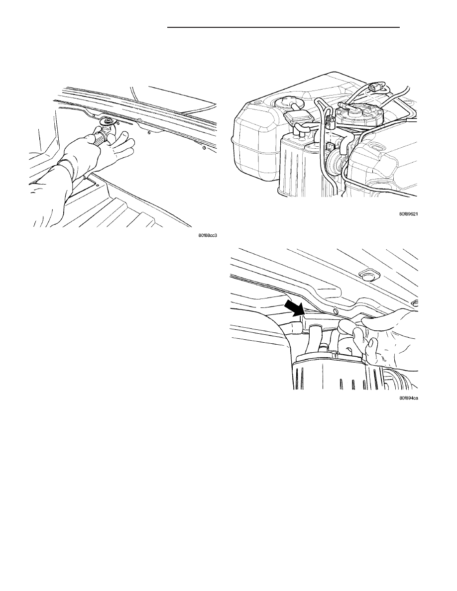
(3) Cut closeout panel hole for fuel tank and
remove panel (Fig. 9).
(4) Drill holes (11 holes).
(5) Disconnect the LDP electrical connector from
pump (Fig. 10).
(6) Remove the liquid separator from the canister
(Fig. 11).
(7) Disconnect lines from LDP.
(8) Remove the EVAP canister.
(9) Remove the three screws from the pump.
INSTALLATION
(1) Install pump to bracket and tighten screws to
1.2 N·m (10.6 in. lbs.).
(2) Before installing hoses to LDP, make sure
they are not cracked or split. If a hose leaks, it
will cause the Check Engine Lamp to illumi-
nate. Connect lines to the LDP.
(3) Install electrical connector to pump and push
locking tab to lock (Fig. 10).
(4) Install the EVAP canister.
(5) Install the liquid separator to the canister (Fig.
11).
(6) Use the DRBIII
t scan tool, verify proper oper-
ation of LDP.
(7) Install the access panel.
(8) Connect the negative battery cable.
Fig. 9 CUTTING PANEL
Fig. 10 FUEL TANK CONNECTORS
Fig. 11 LIQUID SEPARATOR
25 - 14
EVAPORATIVE EMISSIONS
ZB
LEAK DETECTION PUMP (Continued)