Dodge Viper SRT-10 (ZB). Manual - part 274
EVAPORATIVE EMISSIONS
TABLE OF CONTENTS
page
page
EVAPORATIVE EMISSIONS
OPERATION - EVAPORATION CONTROL
. . . . . . . . . . . . . . . . . . . . . . . . . . . . 10
CCV SYSTEM
. . . . . . . . . . . . . . . . . . . . . . . . . 10
. . . . . . . . . . . . . . . . . . . . . . . . . . . 10
DIAGNOSIS AND TESTING - CRANKCASE
. . . . . . . . . . . . . . . . . 11
EVAP/PURGE SOLENOID
. . . . . . . . . . . . . . . . . . . . . . . . . . . 11
. . . . . . . . . . . . . . . . . . . . . . . . . . . . . 12
. . . . . . . . . . . . . . . . . . . . . . . . . 13
FUEL FILLER CAP
. . . . . . . . . . . . . . . . . . . . . . . . . 13
. . . . . . . . . . . . . . . . . . . . . . . . . . . 13
LEAK DETECTION PUMP
. . . . . . . . . . . . . . . . . . . . . . . . . . . . . 13
. . . . . . . . . . . . . . . . . . . . . . . . . 14
ORVR
. . . . . . . . . . . . . . . . . . . . . . . . . 15
. . . . . . . . . . . . . . . . . . . . . . . . . . . 15
VAPOR CANISTER
. . . . . . . . . . . . . . . . . . . . . . . . . 16
. . . . . . . . . . . . . . . . . . . . . . . . . . . 16
. . . . . . . . . . . . . . . . . . . . . . . . . . . . . 16
. . . . . . . . . . . . . . . . . . . . . . . . . 17
EVAPORATIVE EMISSIONS
OPERATION - EVAPORATION CONTROL
SYSTEM
The evaporation control system prevents the emission
of fuel tank vapors into the atmosphere. When fuel
evaporates in the fuel tank, the vapors pass through
vent hoses or tubes to an activated carbon filled evapo-
rative canister. The canister temporarily holds the
vapors. The Powertrain Control Module (PCM) allows
intake manifold vacuum to draw vapors into the com-
bustion chambers during certain operating conditions.
All engines use a duty cycle purge system. The
PCM controls vapor flow by operating the duty cycle
EVAP purge solenoid (Refer to 25 - EMISSIONS
CONTROL/EVAPORATIVE
EMISSIONS/EVAP/
PURGE SOLENOID - OPERATION).
NOTE: The evaporative system uses specially man-
ufactured hoses. they need replacement, only use
fuel resistant hose. Also the hoses must be able to
pass an Ozone compliance test.
CCV SYSTEM
DESCRIPTION
The 8.3L V-10 engine is equipped with a Crankcase
Ventilation (CCV) system. The CCV system performs
the same function as a conventional PCV system, but
use a fixed orifice instead of vacuum controlled valve
(PCV valve).
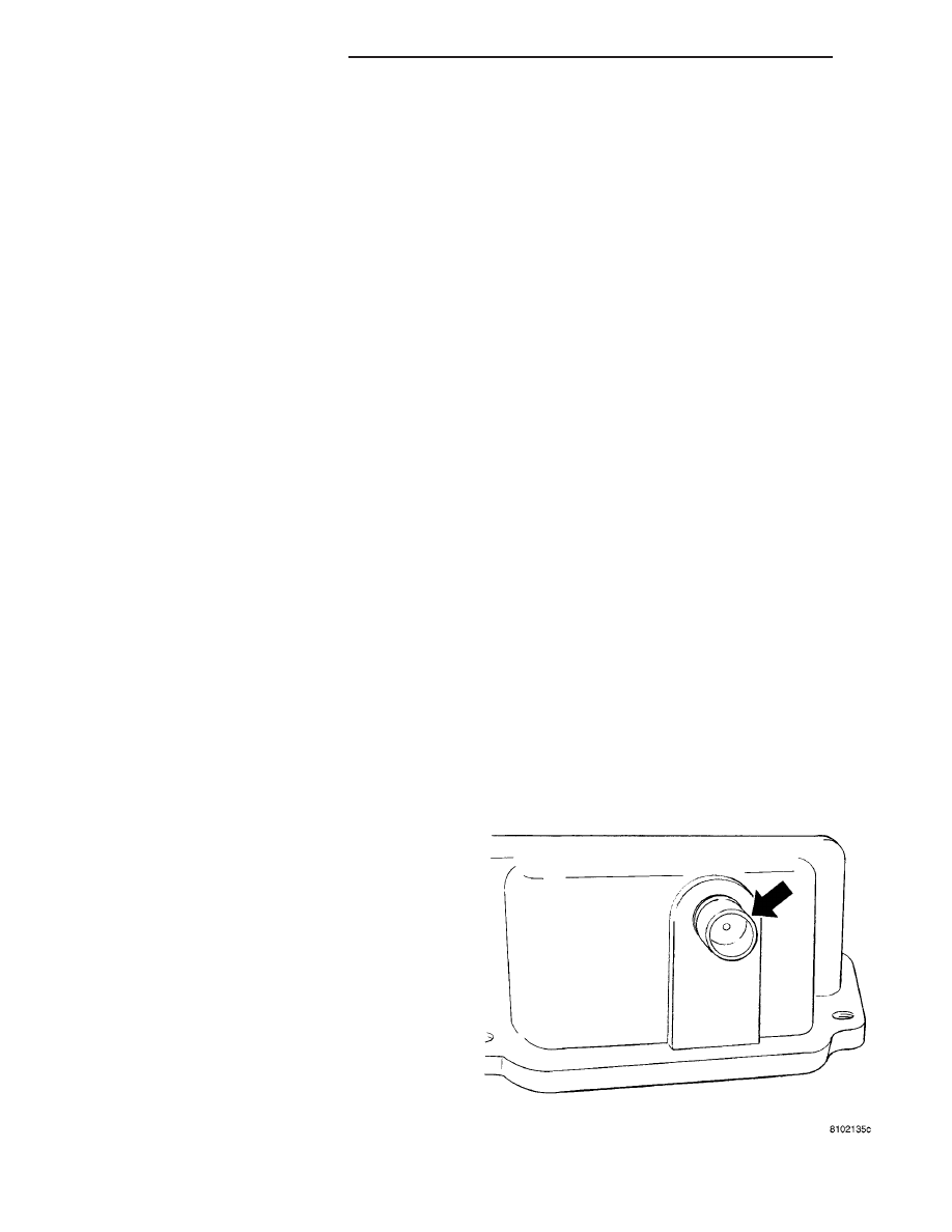
OPERATION
It meters the amount of crankcase vapors drawn
out of the engine. The fixed orifice fitting is
mounted in each of the valve covers in the rear
of the engine (Fig. 1).
When the engine is operating, fresh air enters the
engine and mixes with crankcase vapors. Manifold
vacuum draws the vapor/air mixture through the
fixed orifice and into the intake manifold. The vapors
are then consumed during engine combustion.
Fig. 1 CC LOCATION
25 - 10
EVAPORATIVE EMISSIONS
ZB