Dodge Viper SRT-10 (ZB). Manual - part 266
fold gauge set are opened, the refrigerant in the sys-
tem will escape through this hose.
REFRIGERANT SYSTEM RECOVERY
WARNING: Refer to the applicable warnings and
cautions for this system before performing the fol-
lowing operation (Refer to 24 - HEATING & AIR
CONDITIONING/PLUMBING - WARNINGS) and (Refer
to 24 - HEATING & AIR CONDITIONING/PLUMBING -
CAUTIONS). Failure to follow the warnings and cau-
tions could result in possible personal injury or
death.
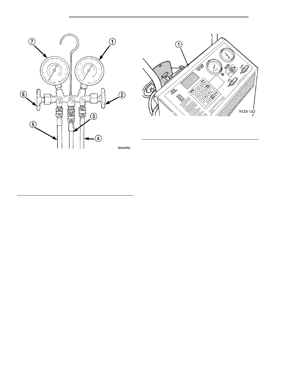
A R-134a refrigerant recovery/recycling/charging
station that meets SAE Standard J2210 must be
used to recover the refrigerant from an R-134a refrig-
erant system (Fig. 3). Refer to the operating instruc-
tions supplied by the equipment manufacturer for
the proper care and use of this equipment.
REFRIGERANT SYSTEM EVACUATE
NOTE: Special effort must be used to prevent mois-
ture from entering the A/C system oil. Moisture in
the oil is very difficult to remove and will cause a
reliability problem with the A/C compressor.
If an A/C compressor designed to use R-134a refrig-
erant is left open to the atmosphere for an extended
period of time. It is recommended that the refriger-
ant oil be drained and replaced with new oil or a new
A/C compressor be used. This will eliminate the pos-
sibility of contaminating the refrigerant system.
If the refrigerant system has been open to the
atmosphere, it must be evacuated before the refriger-
ant system can be filled. Moisture and air mixed
with the refrigerant system will raise the compressor
head pressure above acceptable operating levels. This
will reduce the performance of the A/C system and
damage the A/C compressor. Moisture will boil at
near room temperature when exposed to vacuum. A
R-134a refrigerant recovery/recycling/charging sta-
tion that meets SAE Standard J2210 must be used to
evacuate the refrigerant system. See the operating
instructions supplied by the equipment manufacturer
for proper care and use of this equipment. To evacu-
ate the refrigerant system, use the following proce-
dure:
NOTE: When connecting the service equipment
couplings to the refrigerant system service ports,
be certain that the valve of each coupling is fully
closed. This will reduce the amount of effort
required to make the connection.
(1) Connect a suitable charging station, refrigerant
recovery machine or a manifold gauge set with vac-
uum
pump
and
refrigerant
recovery
equipment
(Refer to 24 - HEATING & AIR CONDITIONING/
PLUMBING - STANDARD PROCEDURE - REFRIG-
ERANT SYSTEM SERVICE EQUIPMENT).
(2) Recover the refrigerant system (Refer to 24 -
HEATING & AIR CONDITIONING/PLUMBING -
Fig. 2 Manifold Gauge Set - Typical
1 - HIGH PRESSURE GAUGE
2 - VALVE
3 - VACUUM/REFRIGERANT HOSE (YELLOW W/ BLACK
STRIPE)
4 - HIGH PRESSURE HOSE (RED W/ BLACK STRIPE)
5 - LOW PRESSURE HOSE (BLUE W/ BLACK STRIPE)
6 - VALVE
7 - LOW PRESSURE GAUGE
Fig. 3 Refrigerant Recovery/Recycling Station -
Typical
1 - R-134a REFRIGERANT STATION
24 - 38
PLUMBING
ZB
PLUMBING (Continued)