Dodge Viper SRT-10 (ZB). Manual - part 210


  Index      Dodge     Dodge Viper SRT-10 (ZB) - service repair manual 2005 year


Search            


Content   ..  208  209  210  211   ..


Dodge Viper SRT-10 (ZB). Manual - part 210


ASSEMBLY - PUMP PULLEY

CAUTION: Do not reuse the old power steering
pump pulley; it is not intended for reuse. A new pul-
ley must be installed if removed.

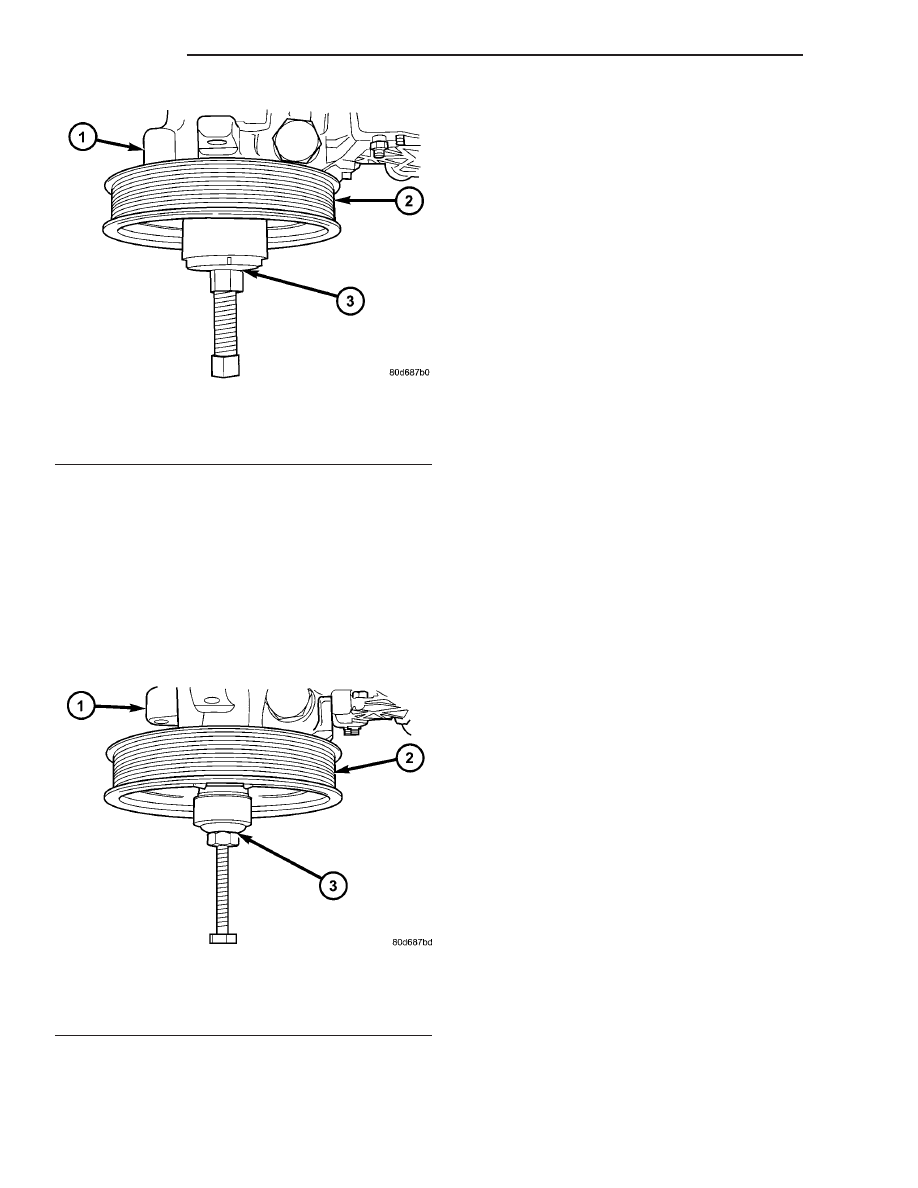
(1) Install pulley on pump with an appropriate

power steering pulley installation tool (Fig. 4).
Ensure tool and pulley remain aligned with pump
shaft during installation. Make sure pulley is flush
with end of shaft.

(2) Install power steering pump assembly on vehi-

cle. (Refer to 19 - STEERING/PUMP - INSTALLA-
TION)

(3) Run engine until warm (5 min.) and note any

belt chirp. If chirp exists, move pulley outward
approximately 0.5 mm (0.020 in.). If noise increases,
press on 1.0 mm (0.040 in.). Be careful that pulley
does not contact mounting bolts.

INSTALLATION

(1) Install power steering pump in reverse order of

removal.

(2) Install three power steering pump mounting

bolts (Fig. 2). Tighten mounting bolts to 23 N·m (200
in. lbs.) torque.

(3) Install return hose from fluid cooler on fitting

of power steering pump reservoir (Fig. 7). Install
hose clamp on return hose past upset bead on power
steering reservoir fitting.

(4) Install return hose from radiator fan on fitting

of power steering pump reservoir (Fig. 7). Install
hose clamp on return hose past upset bead on power
steering reservoir fitting.

(5) Install power steering pressure hose in power

steering pump pressure fitting (Fig. 7). Tighten pres-
sure hose quick-connect fitting to 28 N·m (21 ft. lbs.)
torque.

(6) Connect A/C clutch coil wire connector (Fig. 1).
(7) Install accessory drive belt. (Refer to 7 - COOL-

ING/ACCESSORY DRIVE/DRIVE BELTS - INSTAL-
LATION).

(8) Install air cleaner. (Refer to 9 - ENGINE/AIR

INTAKE SYSTEM - INSTALLATION)

(9) Connect the battery negative (-) cable to bat-

tery negative battery terminal.

CAUTION: Do not use automatic transmission fluid
in power steering system. Only use Mopar

T

Power

Steering Fluid or equivalent.

(10) Fill power steering pump reservoir to correct

fluid level. (Refer to 19 - STEERING/PUMP/FLUID -
STANDARD PROCEDURE)

(11) Perform Power Steering Pump Initial Opera-

tion procedure. (Refer to 19 - STEERING/PUMP -
STANDARD PROCEDURE).

(12) Check for leaks at all hose connections.

FLUID

STANDARD PROCEDURE

STANDARD PROCEDURE - POWER STEERING
FLUID LEVEL CHECKING

WARNING: FLUID LEVEL SHOULD BE CHECKED
WITH THE ENGINE OFF TO PREVENT INJURY
FROM MOVING PARTS.

Fig. 3 Pulley Remover Installed

1 - POWER STEERING PUMP
2 - PULLEY
3 - POWER STEERING PULLEY REMOVAL TOOL

Fig. 4 Pulley Installer Installed

1 - POWER STEERING PUMP
2 - PULLEY
3 - POWER STEERING PUMP PULLEY INSTALLATION TOOL

19 - 28

PUMP

ZB

PUMP (Continued)

CAUTION: Do not use automatic transmission fluid
in this power steering system.

The fluid level should be within the “COLD

RANGE” listed on the dipstick when the fluid is at
normal ambient temperature, approximately 21°C to
27°C (70°F to 80°F).

Before removing the power steering filler cap/dip-

stick, wipe the reservoir filler cap/dipstick free of dirt
and debris. Do not overfill the power steering system.
Use

only

Mopar

t

Power

Steering

Fluid

(MS-5931), or equivalent in this power steering
system.

STANDARD PROCEDURE - FLUSHING POWER
STEERING SYSTEM

WARNING: SAFETY GOGGLES SHOULD BE WORN
AT ALL TIMES DURING THE FOLLOWING PROCE-
DURE TO AVOID PERSONAL INJURY.

Flushing is required when the power steering sys-

tem fluid has become contaminated. Contaminated
fluid in the steering system can cause seal deteriora-
tion and affect steering gear spool valve operation.

(1) Raise the front end of the vehicle off the

ground enough to allow the front wheels to freely
turn.

(2) Remove the return hose from the pump.
(3) Plug the return hose port on the pump.
(4) Place the open end of the return hose into a

large container to catch the draining fluid.

WARNING: ENGINE WILL BE RUNNING AS FLUID IS
ADDED TO PUMP FLUID RESERVOIR. TO AVOID
PERSONAL INJURY, BEWARE OF MOVING ENGINE
PARTS.

CAUTION: Do not reuse any drained power steering
fluid. Use only fresh Mopar

T

power steering fluid or

equivalent.

(5) While an assistant is carefully filling the pump

reservoir with fresh power steering fluid, start the
engine.

(6) With the engine running at idle, turn the wheel

back and forth.

CAUTION: Do not contact or hold the wheel against
the steering stops.

(7) Run approximately a quart of fluid through the

system, then stop the engine and install the return
hose back on the pump.

(8) Fill the system with fresh fluid and perform

the Power Steering Pump Initial Operation proce-
dure listed in this section of the service manual

(Refer to 19 - STEERING/PUMP - STANDARD PRO-
CEDURE).

(9) Start the engine and allow it to run for fifteen

minutes, then stop the engine.

(10) Remove the return hose from the pump and

plug the return hose port on the pump.

(11) Pour fresh power steering fluid into the reser-

voir and check the fluid draining from the return
hose for contamination. If the fluid is still contami-
nated, disassemble and clean the power steering
components as necessary, then repeat the system
flush again as outlined above.

(12) Install the return hose back on the pump,

then perform the Power Steering Pump Initial Oper-
ation procedure (Refer to 19 - STEERING/PUMP -
STANDARD PROCEDURE).

FLUID COOLER

REMOVAL

NOTE: Review all Warnings and Cautions. (Refer to
19 - STEERING - WARNING).

CAUTION: Cap all open ends of power steering
hoses, power steering pump fittings and steering
gear ports when disconnected. This will prevent the
entry of foreign material into the components dur-
ing servicing.

(1) Disconnect negative (-) cable from battery and

isolate cable.

(2) Siphon power steering fluid from fluid reser-

voir.

(3) Raise vehicle. (Refer to LUBRICATION &

MAINTENANCE/HOISTING - STANDARD PROCE-
DURE)

(4) Place several absorbent shop cloths behind

grille opening below cooler tube nuts to catch any
fluid loss during hose removal.

(5) Working through grille opening using Remover,

Special Tool 8875, disconnect hose tubes at cooler
(Fig. 5). Quick-connect tube nuts stay in cooler.

(6) Cap open ends of hose tubes to keep debris out.
(7) Remove screws fastening cooler in place (Fig.

6). Lift cooler off locating pins and remove cooler
through grille opening.

(8) If replacing cooler, unthread and remove tube

nuts from fluid ports as necessary.

INSTALLATION

(1) If necessary, thread tube nuts into fluid ports

of cooler. Tighten tube nuts to 15 N·m (130 in. lbs.)
torque.

ZB

PUMP

19 - 29

FLUID (Continued)

(2) Position cooler and install screws fastening

cooler in place (Fig. 6). Tighten screws to 5 N·m (40
in. lbs.) torque.

(3) Remove any caps on hose tubes and wipe ends

clean.

(4) Slide hose tubes into quick-connect tube nuts

in cooler (Fig. 6). Make sure tubes are locked into
tube nuts.

(5) Lower vehicle.
(6) Connect negative (-) cable to battery.

CAUTION: Do not use automatic transmission fluid
in power steering system. Only use Mopar

T

Power

Steering Fluid or equivalent.

(7) Fill power steering pump reservoir to correct

fluid level. (Refer to 19 - STEERING/PUMP/FLUID -
STANDARD PROCEDURE)

(8) Perform Power Steering Pump Initial Opera-

tion procedure. (Refer to 19 - STEERING/PUMP -
STANDARD PROCEDURE).

(9) Check for leaks.

HOSE - PRESSURE - PUMP TO
FAN

REMOVAL

NOTE: Review all Warnings and Cautions. (Refer to
19 - STEERING - WARNING).

CAUTION: Cap all open ends of power steering
hoses, power steering pump fittings and steering
gear ports when disconnected. This will prevent the
entry of foreign material into the components dur-
ing servicing.

(1) Disconnect negative (-) cable from battery and

isolate cable.

(2) Remove air cleaner housing. (Refer to 9 -

ENGINE/AIR

INTAKE

SYSTEM/AIR

CLEANER

HOUSING - REMOVAL)

(3) Siphon power steering fluid from fluid reser-

voir.

(4) Unthread power steering pressure hose quick-

connect from power steering pump pressure fitting
(Fig. 7). Drain excess power steering fluid from line.

(5) Unthread power steering pressure hose quick-

connect from hydraulic fan (Fig. 7). Drain excess
power steering fluid from line.

(6) Remove power steering pressure hose from

routing clip on cooling module (Fig. 7). Remove hose.

INSTALLATION

NOTE:

Before

installing

power

steering

hose,

replace used O-rings as necessary. Clean hose
ends and open ports with a lint-free cloth. Lubricate
O-rings with clean power steering fluid.

(1) If pressure hose is separate from quick-connect

fittings:

(a) Thread quick-connect fitting into cooling fan

port (Fig. 7). Tighten fitting to 28 N·m (21 ft. lbs.)
torque.

Fig. 5 Using 8875 To Disconnect Quick-Connect

1 - PLACE TOOL 8875 AROUND TUBE AS SHOWN
2 - CLOSE TOOL AROUND TUBE
3 - SLIDE TOOL UP TO TUBE NUT, THEN ROTATE TOOL TO
DISENGAGE RETAINER WHILE PULLING TUBE AWAY FROM
TUBE NUT

Fig. 6 Power Steering Cooler

1 - MOUNTING SCREWS
2 - POWER STEERING COOLER
3 - TUBE NUT - HOSE TO RESERVOIR
4 - TUBE NUT - HOSE FROM GEAR

19 - 30

PUMP

ZB

FLUID COOLER (Continued)

(b) Slide fan end of pressure hose tube into

quick-connect fitting until it locks into place.
(2) If pressure hose has quick-connect fittings

installed on ends, thread fan end quick-connect fit-
ting into fan port. Tighten hose fitting to 28 N·m (21
ft. lbs.) torque.

(3) Install power steering pressure hose into rout-

ing clip on cooling module (Fig. 7).

(4) If pressure hose is separate from quick-connect

fittings:

(a) Thread

quick-connect

fitting

into

power

steering pump pressure fitting (Fig. 7). Tighten
hose fitting to 28 N·m (21 ft. lbs.) torque.

(b) Slide pump end of pressure hose tube into

quick-connect fitting until it locks into place.
(5) If pressure hose has quick-connect fittings

installed on ends, thread pump end quick-connect fit-
ting into power steering pump pressure fitting (Fig.
7). Tighten fitting to 28 N·m (21 ft. lbs.) torque.

(6) Install air cleaner. (Refer to 9 - ENGINE/AIR

INTAKE SYSTEM - INSTALLATION)

(7) Connect the battery negative (-) cable to bat-

tery negative battery terminal.

CAUTION: Do not use automatic transmission fluid
in power steering system. Use only Mopar

T

Power

Steering Fluid or equivalent.

(8) Fill power steering pump reservoir to correct

fluid level. (Refer to 19 - STEERING/PUMP/FLUID -
STANDARD PROCEDURE)

(9) Perform Power Steering Pump Initial Opera-

tion procedure. (Refer to 19 - STEERING/PUMP -
STANDARD PROCEDURE).

(10) Check for leaks at all hose connections.

HOSE - PRESSURE - FAN TO
GEAR

REMOVAL

NOTE: Review all Warnings and Cautions. (Refer to
19 - STEERING - WARNING).

Fig. 7 Power Steering Hoses

1 - PRESSURE HOSE - PUMP TO FAN
2 - PRESSURE HOSE - FAN TO GEAR
3 - POWER STEERING PUMP
4 - RETURN HOSE ROUTING CLIP
5 - COOLING MODULE
6 - HYDRUAULIC FAN
7 - PRESSURE HOSE ROUTING CLIP
8 - QUICK-CONNECT FITTINGS

9 - RETURN HOSE - FAN TO PUMP
10 - QUICK-CONNECT FITTING
11 - POWER STEERING GEAR
12 - RETURN HOSE - COOLER TO PUMP
13 - QUICK-CONNECT FITTINGS
14 - RETURN HOSE - GEAR TO COOLER
15 - POWER STEERING COOLER

ZB

PUMP

19 - 31

HOSE - PRESSURE - PUMP TO FAN (Continued)


Content   ..  208  209  210  211   ..