Dodge Viper SRT-10 (ZB). Manual - part 184


  Index      Dodge     Dodge Viper SRT-10 (ZB) - service repair manual 2005 year


Search            


Content   ..  182  183  184  185   ..


Dodge Viper SRT-10 (ZB). Manual - part 184


(3) Apply penetrating oil to catalytic converter

V-Band clamp and resonator band clamp (Fig. 8) and
(Fig. 10).

(4) Disconnect downstream oxygen sensor connec-

tor (Fig. 8) and (Fig. 9).

(5) Loosen and remove V-Band clamp at exhaust

manifold flange (Fig. 8). Discard V-Band clamp.

NOTE: Do not reuse V-Band clamp.

(6) Remove “A” pillar support isolator (Fig. 8).
(7) Remove “B” pillar support isolator (Fig. 11).

(8) Loosen band clamp at resonator (Fig. 10).
(9) Remove catalytic converter from resonator.

NOTE: When replacement is required on any com-
ponent of the exhaust system, it is important that
original equipment parts be used for the following
reasons:

Ensure proper alignment with other parts in the

system

Provide acceptable exhaust noise levels

Does not change exhaust system back pres-

sure that could affect emissions and performance

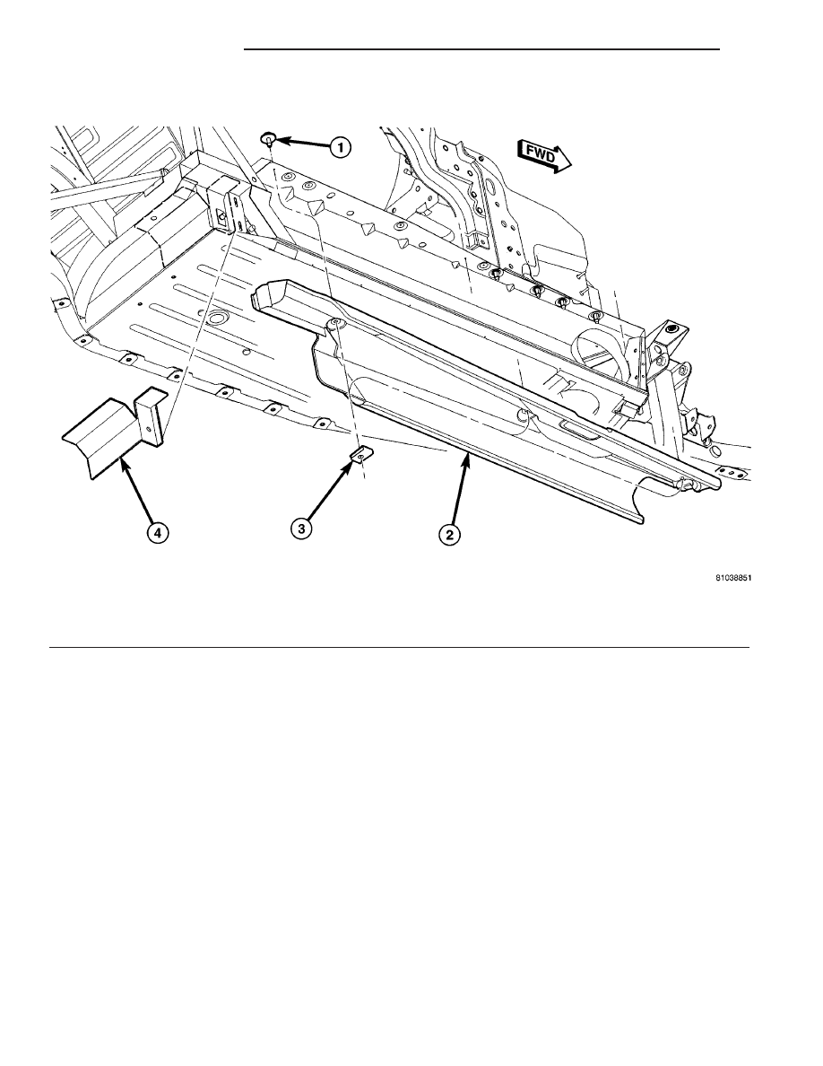
Fig. 6 Inner Sill Heat Shield (Right Side Shown - Left Side Typical)

1 - SCREW(S)
2 - INNER SILL HEAT SHIELD

3 - U NUT
4 - PEEL AND STICK HEAT SHIELD

11 - 6

EXHAUST SYSTEM

ZB

CATALYTIC CONVERTER(S) (Continued)

Fig. 7 Sill Panel (Right Side Shown - Left Side Typical)

1 - FRAME ASSEMBLY
2 - SILL PANEL

3 - FENDER ASSEMBLY

Fig. 8 Catalytic Converter (Right Side Shown - Left

Side Typical)

1 - EXHAUST MANIFOLD
2 - V-BAND CLAMP
3 - CATALYTIC CONVERTER
4 -

9

A

9

PILLAR SUPPORT ISOLATOR

5 - BRACKET
6 - BOLT(S)
7 - DOWNSTREAM OXYGEN SENSOR

Fig. 9 Oxygen Sensors and Connectors (Right Side

Shown - Left Side Typical)

1 - EXHAUST MANIFOLD
2 - UPSTREAM OXYGEN SENSOR
3 - DOWNSTREAM OXYGEN SENSOR CONNECTOR
4 - BODY WIRING
5 - UPSTREAM OXYGEN SENSOR CONNECTOR
6 - TIE WRAP CLIP
7 - DOWNSTREAM OXYGEN SENSOR
8 - RIGHT INNER FRAME RAIL

ZB

EXHAUST SYSTEM

11 - 7

CATALYTIC CONVERTER(S) (Continued)

INSPECTION

WARNING: THE NORMAL OPERATING TEMPERA-
TURE OF THE EXHAUST SYSTEM IS VERY HIGH.
THEREFORE, NEVER ATTEMPT TO SERVICE ANY
PART OF THE EXHAUST SYSTEM UNTIL IT IS
COOLED. SPECIAL CARE SHOULD BE TAKEN
WHEN WORKING NEAR THE CATALYTIC CON-
VERTER. THE TEMPERATURE OF THE CONVERTER
RISES TO A HIGH LEVEL AFTER A SHORT PERIOD
OF ENGINE OPERATION TIME.

Check catalytic converter for a flow restriction.

(Refer to 11 - EXHAUST SYSTEM - DIAGNOSIS
AND TESTING) Exhaust System Restriction Check
for procedure.

Visually inspect the catalytic converter element by

using a borescope or equivalent. Remove oxygen sen-
sor(s) and insert borescope. If borescope is not avail-
able, remove converter and inspect element using a
flashlight. Inspect element for cracked or melted sub-
strate.

NOTE: Before replacing a catalytic converter, deter-
mine the root cause of failure. Most catalytic con-
verter failures are caused by air, fuel or ignition
problems. (Refer to Appropriate Diagnostic Informa-
tion) for test procedures.

INSTALLATION

NOTE: This procedure covers installation of either
the right OR left catalytic converter. Install the
appropriate parts for the side that is being worked
on.

(1) Position catalytic converter to mounting posi-

tion.

(2) Connect resonator to converter. Do not tighten

resonator band clamp at this time to permit align-
ment of all parts.

(3) Loosely

install

a

NEW

V-Band

clamp

at

exhaust manifold to converter pipe connection (Fig.
8).

(4) Loosely install “A” and “B” pillar support isola-

tors (Fig. 8) and (Fig. 11).

(5) Tighten catalytic converter V-Band clamp to 11

N·m (100 in. lbs.) (Fig. 8).

(6) Starting from the front of exhaust system,

align each component to maintain position and
proper clearance with body parts.

(7) Tighten “A” and “B” pillar support isolators to

28 N·m (250 in. lbs.).

(8) Tighten resonator band clamp to 54 N·m (40 ft.

lbs.).

(9) Connect downstream oxygen sensor connector

(Fig. 8) and (Fig. 9).

(10) Install sill panel (Refer to 23 - BODY/EXTE-

RIOR/SILL PANEL - INSTALLATION) (Fig. 7).

(11) Lower vehicle.
(12) Start the engine and inspect for exhaust

leaks. Repair exhaust leaks as necessary.

(13) Check the exhaust system for contact with the

body panels. Make the necessary ajustments, if
needed.

RESONATOR(S)

REMOVAL

NOTE: This procedure covers removal of either the
right OR left resonator. Remove the appropriate
parts for the side that is being worked on.

(1) Raise vehicle on hoist (Refer to LUBRICATION

& MAINTENANCE/HOISTING - STANDARD PRO-
CEDURE).

(2) Remove sill panel (Refer to 23 - BODY/EXTE-

RIOR/SILL PANEL - REMOVAL) (Fig. 7).

(3) Apply penetrating oil to resonator and spout

assembly band clamps (Fig. 10) and (Fig. 11).

(4) Loosen resonator and spout assembly band

clamps (Fig. 10) and (Fig. 11)

(5) Remove “B” pillar support isolator (Fig. 11).
(6) Separate spout assembly from resonator.
(7) Separate resonator from catalytic converter

(Fig. 10).

(8) Remove resonator.

INSTALLATION

NOTE: This procedure covers installation of either
the right OR left resonator. Install the appropriate
parts for the side that is being worked on.

(1) Install resonator to catalytic converter pipe

(Fig. 10). Do not tighten band clamp at this time.

(2) Connect spout assembly to resonator (Fig. 11).

Do not tighten band clamp at this time.

(3) Install “B” pillar support isolator. Tighten bolts

to 28 N·m (250 in. lbs.) (Fig. 11).

(4) Tighten resonator band clamp to 54 N·m (40 ft.

lbs.).

11 - 8

EXHAUST SYSTEM

ZB

CATALYTIC CONVERTER(S) (Continued)

(5) Tighten spout assembly band clamp to 54 N·m

(40 ft. lbs.).

(6) Install sill panel (Refer to 23 - BODY/EXTERI-

OR/SILL PANEL - INSTALLATION) (Fig. 7).

(7) Lower vehicle.
(8) Start the engine and inspect for exhaust leaks.

Repair exhaust leaks as necessary.

(9) Check the exhaust system for contact with the

body panels. Make the necessary ajustments, if
needed.

SPOUT ASSEMBLY - LEFT/
RIGHT

REMOVAL

NOTE: This procedure covers removal of either the
right OR left spout assembly. Remove the appropri-
ate parts for the side that is being worked on.

(1) Raise vehicle on hoist (Refer to LUBRICATION

& MAINTENANCE/HOISTING - STANDARD PRO-
CEDURE).

(2) Remove sill panel (Refer to 23 - BODY/EXTE-

RIOR/SILL PANEL - REMOVAL) (Fig. 7).

(3) Apply penetrating oil to spout assembly and

H-pipe band clamps (Fig. 11) and (Fig. 12).

(4) Loosen

spout

assembly

and

H-Pipe

band

clamps (Fig. 11) and (Fig. 12).

(5) Remove “B” pillar support isolator (Fig. 11).
(6) Separate spout assembly from resonator.
(7) Separate spout assembly from H-Pipe.
(8) Remove spout assembly.

INSTALLATION

NOTE: This procedure covers installation of either
the right OR left spout assembly. Install the appro-
priate parts for the side that is being worked on.

(1) Connect spout assembly to H-Pipe (Fig. 12). Do

not tighten band clamps at this time.

(2) Connect spout assembly to resonator (Fig. 11).

Do not tighten band clamp at this time.

(3) Install “B” pillar support isolator. Tighten bolts

to 28 N·m (250 in. lbs.) (Fig. 11).

(4) Tighten band clamps to 54 N·m (40 ft. lbs.).
(5) Install sill panel (Refer to 23 - BODY/EXTERI-

OR/SILL PANEL - INSTALLATION) (Fig. 7).

(6) Lower vehicle.

Fig. 10 Resonator (Right Side Shown - Left Side

Typical)

1 - CATALYTIC CONVERTER
2 - BAND CLAMP
3 - RESONATOR

Fig. 11 Spout Assembly Mounting (Right Side

Shown - Left Side Typical)

1 - BOLT(S)
2 - BRACKET
3 - BAND CLAMP
4 - SPOUT ASSEMBLY
5 -

9

B

9

PILLAR SUPPORT ISOLATOR

ZB

EXHAUST SYSTEM

11 - 9

RESONATOR(S) (Continued)


Content   ..  182  183  184  185   ..