Dodge Viper SRT-10 (ZB). Manual - part 177


  Index      Dodge     Dodge Viper SRT-10 (ZB) - service repair manual 2005 year


Search            


Content   ..  175  176  177  178   ..


Dodge Viper SRT-10 (ZB). Manual - part 177


(4) Run the transmission to oil pan bolts in finger

tight (Fig. 68).

(5) Torque 5/16–18 oil pan bolts to 23 N·m (200 in.

lbs.). Torque 1/4–20 oil pan bolts to 11 N·m (95 in
lbs.).

(6) Torque transmission to oil pan bolts to 23 N·m

(200 in. lbs.) (Fig. 68).

(7) Install fasteners securing A/C line to oil pan.
(8) Install flywheel inspection cover.
(9) Lower vehicle.
(10) Fill the crankcase with oil to proper level.

OIL PUMP

REMOVAL

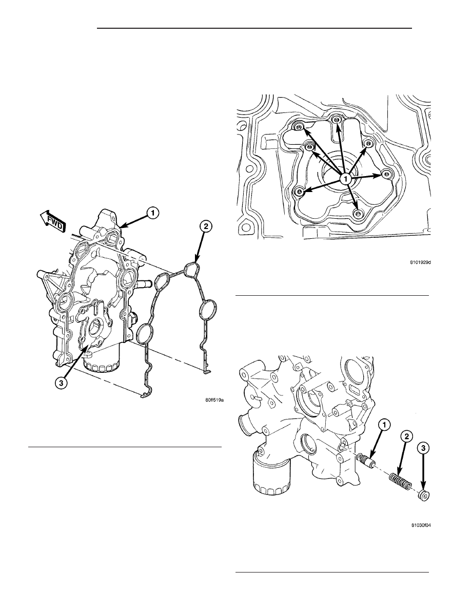
NOTE: The oil pump is serviced with the timing
chain cover (Fig. 70).

(1) Remove timing chain cover (1) (Refer to 9 -

ENGINE/VALVE TIMING/TIMING CHAIN COVER -
REMOVAL).

(2) Disassemble

oil

pump

(3)

(Refer

to

9

-

ENGINE/LUBRICATION/OIL PUMP - DISASSEM-
BLY).

(3) Inspect oil pump parts (Refer to 9 - ENGINE/

LUBRICATION/OIL PUMP - INSPECTION).

DISASSEMBLY

(1) Remove oil pump cover screws (1) and lift off

cover (Fig. 71).

(2) Remove pump rotors.

Fig. 70 Timing Chain Cover and Oil Pump

1 - TIMING CHAIN COVER
2 - SEAL
3 - OIL PUMP

Fig. 71 Oil Pump Cover Screws

1 - SCREWS

Fig. 72 Oil Pressure Relief Valve

1 - OIL PRESSURE RELIEF VALVE
2 - SPRING
3 - PLUG WITH O-RING

9 - 50

ENGINE

ZB

OIL PAN (Continued)

(3) Remove oil pressure relief valve (1) and spring

(2) (Fig. 72).

(4) Wash all parts in a suitable solvent and inspect

carefully for damage or wear.

CLEANING

Clean all parts thoroughly. Mating surface of the

chain case cover should be smooth. Replace pump
cover if scratched or grooved.

INSPECTION

(1) Lay a straightedge (1) across the pump cover

surface (Fig. 73). If a 0.076 mm (0.003 in.) feeler
gauge (2) can be inserted between cover and straight
edge, cover should be replaced.

(2) Measure thickness and diameter of rotors. if

the outer rotor diameter is 82.45 mm (3.246 in.) or
less, replace rotor set (Fig. 74) and (Fig. 75).

(3)

If either rotor thickness measures 18.92 mm

(0.744 in.) or less, replace rotor set

(4) Measure clearance between outer rotor (2) and

case (Fig. 76). If measurement is 0.19 mm (0.007 in.)
or more, and outer rotor (2) is within specification,
replace chain case cover.

Fig. 73 Checking Oil Pump Cover Flatness - Typical

1 - STRAIGHT EDGE
2 - FEELER GAUGE
3 - OIL PUMP COVER

Fig. 74 Measuring Outer Rotor Thickness

Fig. 75 Measuring Inner Rotor Thickness

Fig. 76 Measuring Outer Rotor Clearance in Case

1 - FEELER GUAGE
2 - OUTER ROTOR

ZB

ENGINE

9 - 51

OIL PUMP (Continued)

(5) Measure clearance between the outer rotor (2)

and inner rotor (3) (Fig. 77). If clearance between
inner (3) and outer rotors (2) is 0.150 mm (0.006 in.)
or more, replace rotor set.

(6) Place a straightedge across the face of the chain

case cover, in between the bolt holes. If a feeler gauge of
0.077 mm (0.003 in.) or more can be inserted between
rotors and the straightedge, and the rotors are within
specification, replace the case cover.

(7) Inspect oil pressure relief valve for scoring and

free operation in its bore. Small marks may be
removed with 400 grit wet or dry sandpaper.

(8) The relief valve spring has a free length of

approximately 68.7 mm (2.70 in.) and should test
between 10.2 kg and 12.4 kg (22.5 and 27.5 lbs.)
when compressed to 57 mm (2.24 in.). Replace spring
that fails to meet specifications.

(9) If oil pressure is low and pump is within spec-

ifications, inspect for worn engine bearings or other
reasons for oil pressure loss.

ASSEMBLY

(1) Assemble pump using new parts as required.
(2) Install spring (2) onto oil pressure relief valve (1).
(3) Lubricate oil pressure relief valve and spring

with clean engine oil.

(4) Install oil pressure relief valve (1) and spring (2).
(5) Inspect relief valve plug o-ring (3). Replace as

necessary. Torque plug to 34 N·m (25 ft. lbs.) (Fig. 72)

(6) Install pump rotors with chamfer side to the

inside of chain case cover.

(7) Install oil pump cover and screws (1). Tighten

cover screws to 23 N·m (200 in. lbs.) (Fig. 71).

(8) Prime oil pump before installation by filling

rotor cavity with engine oil.

Fig. 77 Measuring Clearance Between Rotors

1 - FEELER GUAGE
2 - OUTER ROTOR
3 - INNER ROTOR

Fig. 78 Oil Pressure Relief Valve INSTALL

1 - OIL PRESSURE RELIEF VALVE
2 - SPRING
3 - PLUG WITH O-RING

Fig. 79 Oil Pump Cover Screws

1 - SCREWS

9 - 52

ENGINE

ZB

OIL PUMP (Continued)

INSTALLATION

(1) Assemble oil pump (Refer to 9 - ENGINE/LU-

BRICATION/OIL PUMP - ASSEMBLY).

(2) Prime oil pump before installation by filling

rotor cavity with engine oil.

(3) Install

timing

chain

cover

(Refer

to

9

-

ENGINE/VALVE TIMING/TIMING CHAIN COVER -
INSTALLATION).

(4) Install NEW oil filter.
(5) Fill the crankcase with oil to proper level.

OIL PRESSURE SENSOR

REMOVAL

(1) Disconnect oil pressure sensor electrical con-

nector.

(2) Remove oil pressure sensor (Fig. 80).

INSTALLATION

(1) Apply thread sealer to oil pressure sensor

threads.

(2) Install oil pressure sensor (Fig. 80).
(3) Connect electrical connector.

SENSOR-OIL TEMPERATURE

REMOVAL

(1) Disconnect oil temperature sensor electrical

connector.

(2) Remove oil temperature sensor (Fig. 80).

INSTALLATION

(1) Apply thread sealer to oil temperature sensor

threads.

(2) Install oil temperature sensor (Fig. 80).
(3) Connect electrical connector.

ENGINE BLOCK

DESCRIPTION

The cylinder block is made of a sand-cast alumi-

num alloy. The cylinder block has interference-fit cast
iron cylinder liners. The cylinder liners are thermally
installed during block manufacturing; they are not
serviceable items.

Six iron main bearing caps use four bolts per cap;

two vertical and two horizontal. A crankshaft oil
scraper is attached to the main bearing caps via
extended main bearing cap bolts and nuts.

STANDARD PROCEDURE - CYLINDER BORE
HONING

Before honing, stuff plenty of clean shop towels

under the bores and over the crankshaft to keep
abrasive materials from entering the crankshaft
area.

(1) Used carefully, the Cylinder Bore Sizing Hone

C-823, equipped with 220 grit stones, is the best tool
for this job. In addition to deglazing, it will reduce
taper and out-of-round, as well as removing light

Fig. 80 Oil Pressure Sensor and Oil Temperature Sensor

1 - OIL PRESSURE SENSOR
2 - OIL TEMPERATURE SENSOR

Fig. 81 Cylinder Bore Crosshatch Pattern

1 - CROSSHATCH PATTERN
2 - INTERSECT ANGLE

ZB

ENGINE

9 - 53

OIL PUMP (Continued)


Content   ..  175  176  177  178   ..