Dodge Viper SRT-10 (ZB). Manual - part 173
(4) Remove cylinder head cover from engine (Fig.
37).
INSTALLATION
LEFT CYLINDER HEAD COVER
NOTE: Care must be taken to protect the cylinder
head covers powder coating from scrapes and
abrasions.
(1) Inspect cylinder head cover gasket. Replace as
necessary.
(2) Place cylinder head cover onto cylinder head
(Fig. 37). Install and tighten cylinder head cover fas-
teners to 11 N·m (95 in. lbs.) in sequence shown in
(Fig. 38).
(3) Position the oil level indicator tube into posi-
tion. Tighten fastener to 11 N·m (95 in. lbs.).
(4) Connect spark plug wires. Position spark plug
wire retainers onto cylinder head cover studs.
(5) Connect CCV hose to cylinder head cover.
(6) Connect the power brake booster vacuum hose
to the intake manifold port.
RIGHT CYLINDER HEAD COVER
(1) Inspect cylinder head cover gasket. Replace as
necessary.
(2) Place cylinder head cover onto cylinder head
(Fig. 37).
(3) Connect spark plug wires. Position spark plug
wire retainers onto cylinder head cover studs.
(4) Connect CCV hose to cylinder head cover.
ROCKER ARMS
REMOVAL
NOTE: Before replacing parts, inspect all related
valvetrain
components
for
damage
to
prevent
engine misfire.
(1) Remove cylinder head cover(s) (Refer to 9 -
ENGINE/CYLINDER
HEAD/CYLINDER
HEAD
COVER(S) - REMOVAL).
(2) Remove two rocker pedestal bolts per each cyl-
inder (Fig. 33).
(3) Remove rocker arm assemblies as a pair (Fig.
33).
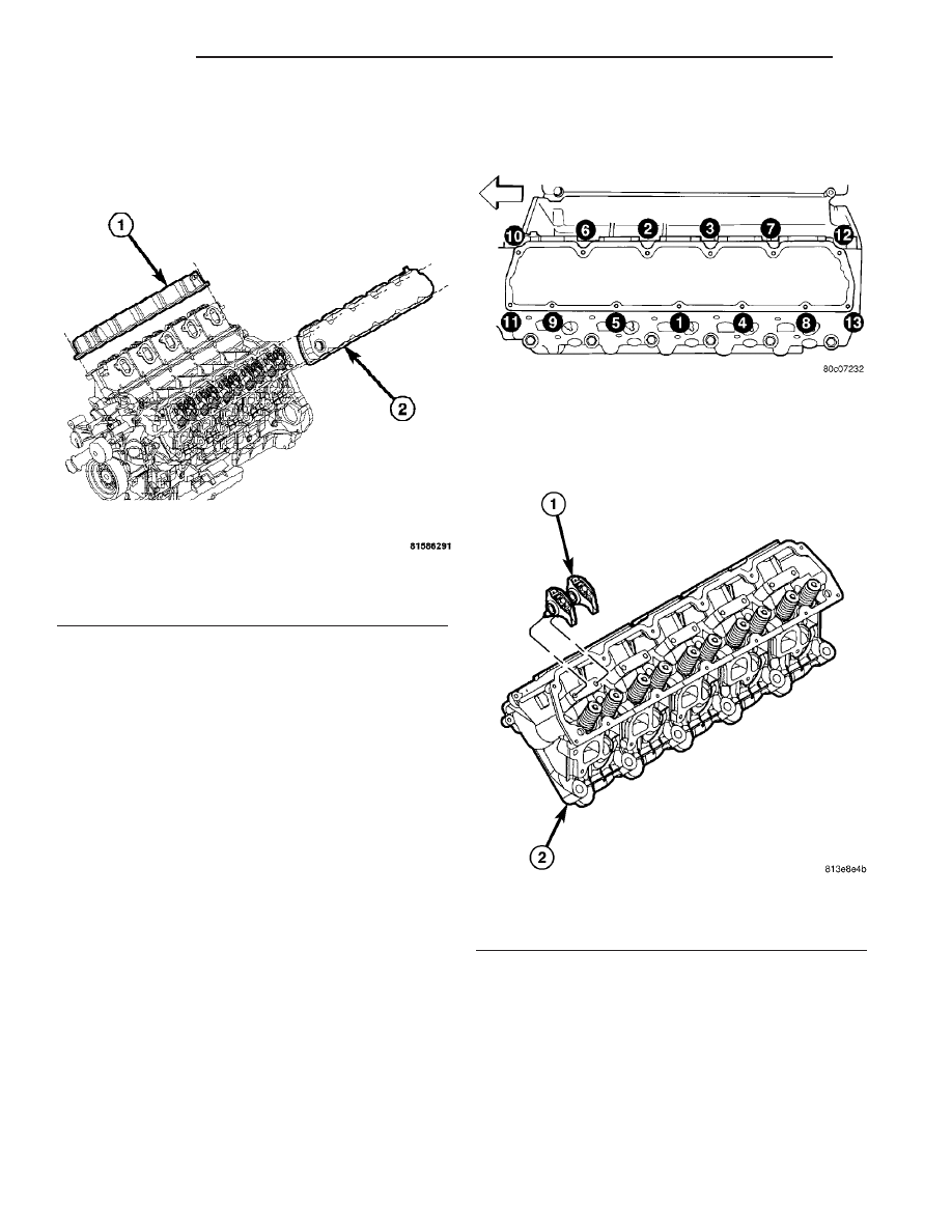
Fig. 37 Cylinder Head Covers
1 - RIGHT CYLINDER HEAD COVER
2 - LEFT CYLINDER HEAD COVER
Fig. 38 Cylinder Head Cover Tightening Sequence
Fig. 39 ROCKER ARMS - 8.3L
1 - ROCKER ARM ASSEMBLY
2 - CYLINDER HEAD
9 - 34
ENGINE
ZB
CYLINDER HEAD COVER(S) (Continued)