Dodge Viper SRT-10 (ZB). Manual - part 167


  Index      Dodge     Dodge Viper SRT-10 (ZB) - service repair manual 2005 year


Search            


Content   ..  165  166  167  168   ..


Dodge Viper SRT-10 (ZB). Manual - part 167


(6) If no leaks are detected, turn off the air supply.

Remove the air hose, all plugs, and caps. Connect the
PCV hoses. Proceed to next step.

(7) Clean the oil off the suspect oil leak area using

a suitable solvent. Drive the vehicle at various
speeds approximately 24 km (15 miles). Inspect the
engine for signs of an oil leak by using a black light.

NOTE: If oil leakage is observed at the dipstick tube
to oil pan location; remove the tube, clean and
reseal using Mopar

T

Stud & Bearing Mount (press

fit tube applications only), and for O-ring style
tubes, remove tube and replace the O-ring seal.

INSPECTION FOR REAR SEAL AREA LEAKS

Since it is sometimes difficult to determine the

source of an oil leak in the rear seal area of the
engine, a more involved inspection is necessary. The
following steps should be followed to help pinpoint
the source of the leak.

If the leakage occurs at the crankshaft rear oil seal

area:

(1) Disconnect the battery.
(2) Raise the vehicle.
(3) Remove clutch housing inspection cover and

inspect rear of block for evidence of oil. Use a black
light to check for the oil leak. If a leak is present in
this area, remove transmission for further inspection.

(a) Circular spray pattern generally indicates

seal leakage or crankshaft damage.

(b) Where leakage tends to run straight down,

possible causes are a porous block, oil gallery cup
plug or rear crankshaft seal retainer gasket leak.
See proper repair procedures for these items.
(4) If no leaks are detected, pressurize the crank-

case as previously described.

CAUTION: Do not exceed 20.6 kPa (3 psi).

(5) If the leak is not detected, very slowly turn the

crankshaft and watch for leakage. If a leak is
detected between the crankshaft and seal while
slowly turning the crankshaft, it is possible the
crankshaft seal surface is damaged. The seal area on
the crankshaft could have minor nicks or scratches
that can be polished out with emery cloth.

CAUTION: Use extreme caution when crankshaft
polishing is necessary to remove minor nicks and
scratches. The crankshaft seal flange is especially
machined to complement the function of the rear oil
seal.

(6) For bubbles that remain steady with shaft

rotation, no further inspection can be done until dis-
assembled.

(7) After the oil leak root cause and appropriate

corrective action have been identified, replace compo-
nent(s) as necessary.

STANDARD PROCEDURE

ENGINE CORE AND OIL GALLERY PLUGS

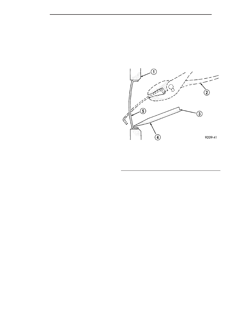
Using a blunt tool such as a drift (4) and a ham-

mer, strike the bottom edge of the cup plug. With the
cup plug rotated, grasp firmly with pliers (2) or other
suitable tool and remove plug (5) (Fig. 3).

CAUTION: Do not drive cup plug into the casting as
restricted cooling can result and cause serious
engine problems.

Thoroughly clean inside of cup plug hole in cylin-

der block or head. Be sure to remove old sealer.
Lightly coat inside of cup plug hole with Mopar

t

Stud and Bearing Mount. Make certain the new plug
is cleaned of all oil or grease. Using proper drive
plug, drive plug into hole so that the sharp edge of
the plug is at least 0.5 mm (0.020 in.) inside the
lead-in chamfer.

It is not necessary to wait for curing of the sealant.

The cooling system can be refilled and the vehicle
placed in service immediately.

FORM-IN-PLACE GASKETS AND SEALERS

There are numerous places where form-in-place

gaskets are used on the engine. Care must be taken
when

applying

form-in-place

gaskets

to

assure

obtaining the desired results. Do not use form-in-

Fig. 3 Core Hole Plug Removal

1 - CYLINDER BLOCK
2 - REMOVE PLUG WITH PLIERS
3 - STRIKE HERE WITH HAMMER
4 - DRIFT PUNCH
5 - CUP PLUG

9 - 10

ENGINE

ZB

ENGINE - 8.3L (Continued)

place gasket material unless specified. Bead size,
continuity, and location are of great importance. Too
thin a bead can result in leakage while too much can
result in spill-over which can break off and obstruct
fluid feed lines. A continuous bead of the proper
width is essential to obtain a leak-free gasket.

There are numerous types of form-in-place gasket

materials that are used in the engine area. Mopar

t

Engine RTV GEN II, Mopar

t ATF-RTV, and Mopart

Gasket Maker gasket materials, each have different
properties and can not be used in place of the other.

MOPAR

ENGINE RTV GEN II

Mopar

t Engine RTV GEN II is used to seal com-

ponents exposed to engine oil. This material is a spe-
cially designed black silicone rubber RTV that
retains

adhesion

and

sealing

properties

when

exposed to engine oil. Moisture in the air causes the
material to cure. This material is available in three
ounce tubes and has a shelf life of one year. After one
year this material will not properly cure. Always
inspect the package for the expiration date before
use.

MOPAR

ATF RTV

Mopar

t ATF RTV is a specifically designed black

silicone rubber RTV that retains adhesion and seal-
ing properties to seal components exposed to auto-
matic

transmission

fluid,

engine

coolants,

and

moisture. This material is available in three ounce
tubes and has a shelf life of one year. After one year
this material will not properly cure. Always inspect
the package for the expiration date before use.

MOPAR

GASKET MAKER

Mopar

t Gasket Maker is an anaerobic type gasket

material. The material cures in the absence of air
when squeezed between two metallic surfaces. It will
not cure if left in the uncovered tube. The anaerobic
material is for use between two machined surfaces.
Do not use on flexible metal flanges.

MOPAR

BED PLATE SEALANT

Mopar

t Bed Plate Sealant is a unique (green-in-

color) anaerobic type gasket material that is specially
made to seal the area between the bedplate and cyl-
inder block without disturbing the bearing clearance
or alignment of these components. The material
cures slowly in the absence of air when torqued
between two metallic surfaces, and will rapidly cure
when heat is applied.

MOPAR

GASKET SEALANT

Mopar

t Gasket Sealant is a slow drying, perma-

nently soft sealer. This material is recommended for
sealing threaded fittings and gaskets against leakage
of oil and coolant. Can be used on threaded and
machined parts under all temperatures. This mate-
rial is used on engines with multi-layer steel (MLS)
cylinder head gaskets. This material also will pre-
vent corrosion. Mopar

t Gasket Sealant is available in

a 13 oz. aerosol can or 4 oz./16 oz. can w/applicator.

FORM-IN-PLACE GASKET AND SEALER
APPLICATION

Mopar

t Gasket Maker material should be applied

sparingly 1 mm (0.040 in.) diameter or less of sealant
to one gasket surface. Be certain the material sur-
rounds each mounting hole. Excess material can eas-
ily be wiped off. Components should be torqued in
place within 15 minutes. The use of a locating dowel
is recommended during assembly to prevent smear-
ing material off the location.

Mopar

t Engine RTV GEN II or ATF RTV gasket

material should be applied in a continuous bead
approximately 3 mm (0.120 in.) in diameter. All
mounting holes must be circled. For corner sealing, a
3.17 mm or 6.35 mm (1/8 in. or 1/4 in.) drop is placed
in the center of the gasket contact area. Uncured
sealant may be removed with a shop towel. Compo-
nents should be torqued in place while the sealant is
still wet to the touch (within 10 minutes). The usage
of a locating dowel is recommended during assembly
to prevent smearing material off the location.

Mopar

t Gasket Sealant in an aerosol can should be

applied using a thin, even coat sprayed completely
over both surfaces to be joined, and both sides of a
gasket. Then proceed with assembly. Material in a
can w/applicator can be brushed on evenly over the
sealing surfaces. Material in an aerosol can should be
used on engines with multi-layer steel gaskets.

ZB

ENGINE

9 - 11

ENGINE - 8.3L (Continued)

ENGINE GASKET SURFACE PREPARATION

To ensure engine gasket sealing, proper surface

preparation must be performed, especially with the
use of aluminum engine components and multi-layer
steel cylinder head gaskets.

Never use the following to clean gasket surfaces:
• Metal scraper

• Abrasive pad or paper to clean cylinder block

and head

• High speed power tool with an abrasive pad or a

wire brush (1) (Fig. 4)

NOTE: Multi-Layer Steel (MLS) head gaskets require
a scratch free sealing surface.

Only use the following for cleaning gasket surfaces:
• Solvent or a commercially available gasket

remover

• Plastic or wood scraper (3) (Fig. 4)

• Drill motor with 3M Roloc™ Bristle Disc (white

or yellow) (2) (Fig. 4)

CAUTION: Excessive pressure or high RPM (beyond
the recommended speed), can damage the sealing
surfaces. The mild (white, 120 grit) bristle disc is
recommended. If necessary, the medium (yellow, 80
grit) bristle disc may be used on cast iron surfaces
with care.

HYDROSTATIC LOCKED ENGINE

When an engine is suspected to be hydrostatically

locked, regardless of what caused the problem, the
following steps should be used.

CAUTION: DO NOT use starter motor to rotate the
engine, severe damage may occur.

(1) Inspect

air

cleaner,

induction

system

and

intake manifold to ensure system is dry and clear of
foreign material.

(2) Remove negative battery cable.
(3) Place a shop towel around the spark plugs

when removing them from the engine. This will catch
any fluid that may possibly be in the cylinder under
pressure.

(4) With all spark plugs removed, rotate engine

crankshaft using a breaker bar and socket.

(5) Identify the fluid in the cylinder(s) (i.e., cool-

ant, fuel, oil or other).

(6) Make sure all fluid has been removed from the

cylinders. Inspect engine for damage (i.e., connecting
rods, pistons, valves, etc.)

(7) Repair engine or components as necessary to

prevent this problem from re-occurring.

CAUTION: Squirt approximately one teaspoon of oil
into the cylinders, rotate engine to lubricate the cyl-
inder walls to prevent damage on restart.

(8) Install new spark plugs.
(9) Drain engine oil and remove oil filter.
(10) Fill engine with specified amount of approved

oil and install new oil filter.

(11) Connect negative battery cable.
(12) Start engine and check for any leaks.

REMOVAL - ENGINE ASSEMBLY

NOTE: For Special Tool identification, (Refer to 9 -
ENGINE - SPECIAL TOOLS).

(1) Perform fuel pressure release procedure (Refer

to 14 - FUEL SYSTEM/FUEL DELIVERY - STAN-
DARD PROCEDURE - FUEL SYSTEM PRESSURE
RELEASE PROCEDURE).

(2) Open trunk lid. Remove battery cover. Discon-

nect negative battery cable.

(3) Remove hood (Refer to 23 - BODY/HOOD/

HOOD - REMOVAL).

(4) Disconnect throttle body air inlet hose, remove

air cleaner housing assembly (Refer to 9 - ENGINE/
AIR INTAKE SYSTEM - REMOVAL).

(5) Drain cooling system (Refer to 7 - COOLING/

ENGINE - STANDARD PROCEDURE - DRAINING
COOLING SYSTEM).

Fig. 4 Proper Tool Usage For Surface Preparation

1 - ABRASIVE PAD
2 - 3M ROLOC™ BRISTLE DISC
3 - PLASTIC/WOOD SCRAPER

9 - 12

ENGINE

ZB

ENGINE - 8.3L (Continued)

(6) Discharge air conditioning system using a suit-

able refrigerant recovery machine (Refer to 24 -
HEATING & AIR CONDITIONING/PLUMBING/RE-
FRIGERANT - STANDARD PROCEDURE).

(7) Remove front strut tower to tower brace (Fig.

5) (Refer to 23 - BODY/EXTERIOR/FRONT STRUT
TOWER TO TOWER BRACE - REMOVAL).

(8) Remove upper radiator hose from the engine.
(9) Remove accessory drive belt (Refer to 7 -

COOLING/ACCESSORY

DRIVE/DRIVE

BELT

-

REMOVAL).

(10) Remove power steering pump mounting bolts

and set pump aside. Do not disconnect lines.

(11) Disconnect and remove generator.
(12) Disconnect heater hoses from engine.
(13) Disconnect coolant bottle inlet hose from ther-

mostat housing.

(14) Disconnect PCM engine electrical connectors.

Disconnect ground wire from stud at left side frame
rail.

(15) Remove windshield wiper arms (Refer to 8 -

ELECTRICAL/WIPERS/WASHERS/WIPER ARMS -
REMOVAL).

(16) Remove cowl cover (Refer to 23 - BODY/EX-

TERIOR/COWL COVER - REMOVAL).

(17) Disconnect brake booster vacuum hose, evap-

orative emission harness, fuel line and accelerator
cable.

(18) Disconnect A/C lines from A/C compressor.

Plug holes in A/C compressor to prevent debris from
entering A/C compressor.

(19) Disconnect A/C clutch electrical connector.

(20) Remove left and right side sill panels (Refer

to 23 - BODY/EXTERIOR/SILL PANEL - REMOVAL)
(Fig. 6).

(21) Remove gear shifter trim bezel and gear shift

lever.

(22) Raise vehicle on hoist.
(23) Remove under body stone shields.

Fig. 5 Front Strut Tower to Tower Brace

1 - FRONT STRUT TOWER TO TOWER BRACE
2 - MOUNTING BOLTS

Fig. 6 Sill Panel (Right Side Shown - Left Side Typical)

1 - FRAME ASSEMBLY
2 - SILL PANEL

3 - FENDER ASSEMBLY

ZB

ENGINE

9 - 13

ENGINE - 8.3L (Continued)


Content   ..  165  166  167  168   ..