Dodge Viper SRT-10 (ZB). Manual - part 83
POWER MIRROR SWITCH TEST
SWITCH POSITION
CONTINUITY BETWEEN
MIRROR SELECT SWITCH IN
9
LEFT
9
POSITION
UP
3 AND 1
7 AND 8
DOWN
3 AND 8
1 AND 7
LEFT
7 AND 1
3 AND 4
RIGHT
3 AND 1
7 AND 4
MIRROR SELECT SWITCH IN
9
RIGHT
9
POSITION
UP
7 AND 2
10 AND 3
DOWN
10 AND 7
2 AND 3
LEFT
10AND 7
9 AND 3
RIGHT
9 AND 7
10 AND 3
REMOVAL
(1) Disconnect and isolate the battery negative
cable.
(2) Remove the door trim panel (Refer to 23 -
BODY/DOOR - FRONT/TRIM PANEL - REMOVAL).
(3) Disconnect the electrical harness connector and
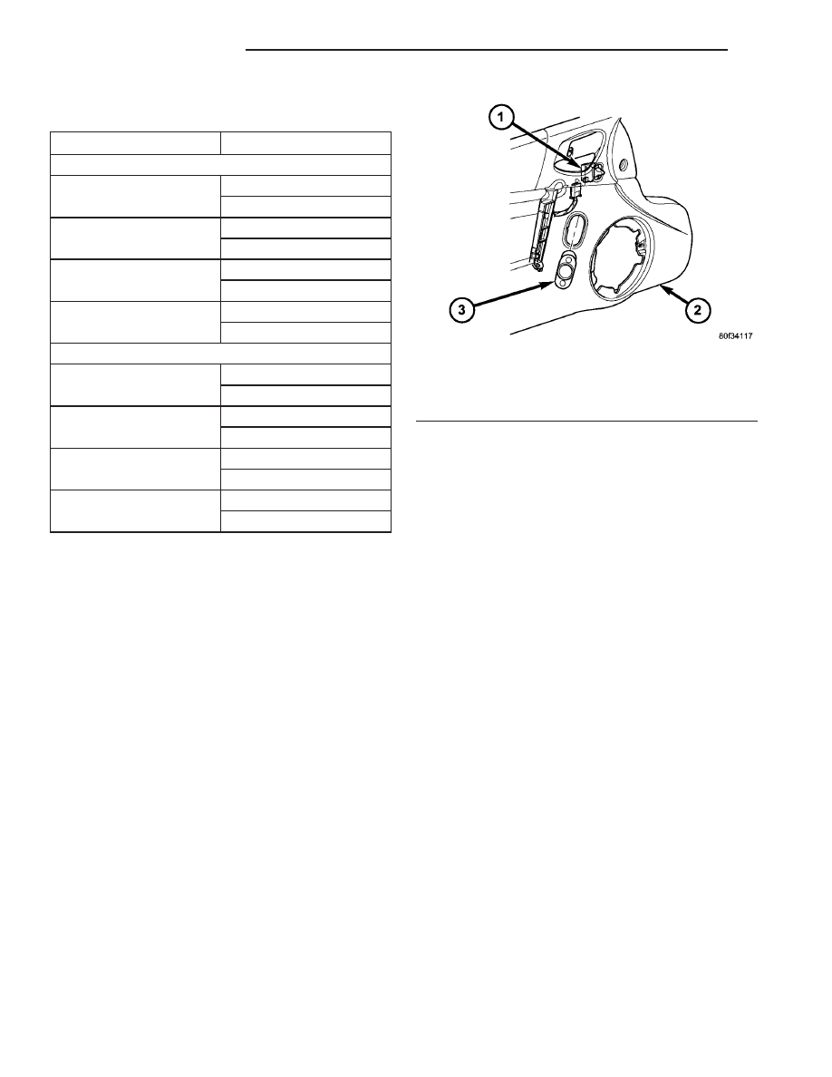
remove switch (Fig. 2).
INSTALLATION
(1) Install switch to door trim panel and connect
electrical harness connector.
(2) Install door trim panel (Refer to 23 - BODY/
DOOR - FRONT/TRIM PANEL - INSTALLATION).
(3) Connect battery negative cable.
SIDEVIEW MIRROR
DESCRIPTION
Each power mirror head contains two electric
motors, two drive mechanisms, and the mirror glass.
One motor and drive controls mirror vertical move-
ment, and the other controls horizontal movement.
The power mirror assembly cannot be repaired. If
any component of the power mirror unit is faulty or
damaged, the entire assembly must be replaced.
(Refer to 23 - BODY/EXTERIOR/SIDE VIEW MIR-
ROR - REMOVAL).
OPERATION
When the mirror is supplied with battery current
and ground, it moves the mirror glass through its
drive unit in one direction. When the battery current
and ground feeds to the motor are reversed, it moves
the mirror case and glass in the opposite direction.
Fig. 2 POWER MIRROR SWITCH
1 - POWER LOCK SWITCH
2 - DOOR TRIM PANEL
3 - POWER MIRROR SWITCH
8N - 8
POWER MIRRORS
ZB
POWER MIRROR SWITCH (Continued)