Dodge Viper SRT-10 (ZB). Manual - part 45
 

  Index      Dodge     Dodge Viper SRT-10 (ZB) - service repair manual 2005 year


Search            


Content   ..  43  44  45  46   ..


Dodge Viper SRT-10 (ZB). Manual - part 45


NOTE: For assembly, (Refer to 5 - BRAKES - ABS/
HYDRAULIC/MECHANICAL/ICU (INTEGRATED CON-
TROL UNIT) - ASSEMBLY).

ASSEMBLY

(1) Install the CAB on the HCU lining up the sole-

noids with the valves.

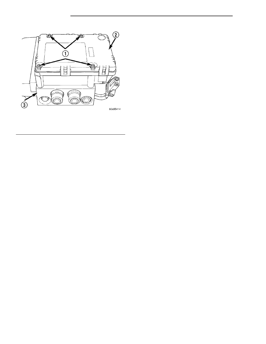
(2) Install the 4 bolts mounting the CAB to the

HCU (Fig. 12). Tighten the CAB mounting bolts to a
torque of 2 N·m (17 in. lbs.).

(3) Plug the pump/motor wiring harness into the

CAB (Fig. 11).

(4) Install the ICU in the vehicle. (Refer to 5 -

BRAKES/HYDRAULIC/MECHANICAL/ICU

(INTE-

GRATED CONTROL UNIT) - INSTALLATION)

INSTALLATION

(1) Install ICU onto its mounting bracket.
(2) Install three bolts attaching ICU to mounting

bracket (Fig. 10). Tighten mounting bolts to 10 N·m
(85 in. lbs.) torque.

(3) Install primary and secondary brake tubes

from the master cylinder at ICU hydraulic control
unit (Fig. 9). Tighten primary and secondary brake
tube nuts to 17 N·m (145 in. lbs.) torque.

(4) Install three chassis brake tubes into their

respective outlet ports in ICU hydraulic control unit.
(Fig. 9). Tighten three brake tube nuts to 17 N·m
(145 in. lbs.) torque.

CAUTION: Before installing the 24-way connector in
the CAB, be sure the seal is properly installed in
the connector.

(5) Install 24-way connector into socket of CAB as

follows:

(a) Position 24-way connector in socket of CAB

and carefully push it down as far as possible.

(b) Once connector is fully seated into CAB

socket, push connector lock inward. This pulls con-
nector into socket of CAB and locks it in place.
(6) Install belly pan front extension. (Refer to 23 -

BODY/EXTERIOR/BELLY PAN - INSTALLATION)

(7) Install access panel in forward portion of left

front wheel well.

(8) Install tire and wheel assembly (Refer to 22 -

TIRES/WHEELS - INSTALLATION). Progressively
tighten the wheel mounting nuts in the proper
sequence to 122 N·m (90 ft. lbs.) torque.

(9) Lower vehicle.
(10) Connect battery negative (-) terminal to bat-

tery post.

NOTE: The ICU may need to be initialized using the

(11) Remove brake pedal prop.
(12) Connect DRBIII

t to data link connector below

steering column to initialize new CAB. Check for any
faults. Refer to Appropriate Diagnostic Information.

(13) Bleed base brakes and ABS, then repeat

bleeding base brake hydraulic system. (Refer to 5 -
BRAKES - ABS - STANDARD PROCEDURE)

(14) Fill master cylinder to proper fill level.
(15) Road test vehicle to ensure proper operation

of base and antilock brake systems.

Fig. 12 CAB Attaching Bolts (Typical)

1 - MOUNTING BOLTS
2 - CAB
3 - HCU VALVE BLOCK

5 - 58

BRAKES - ABS

ZB

ICU (INTEGRATED CONTROL UNIT) (Continued)

CLUTCH

TABLE OF CONTENTS

page

page

CLUTCH

DESCRIPTION

. . . . . . . . . . . . . . . . . . . . . . . . . . 1

OPERATION

. . . . . . . . . . . . . . . . . . . . . . . . . . . . 2

WARNING

. . . . . . . . . . . . . . . . . . . . . . . . . . . . . 3

DIAGNOSIS AND TESTING - CLUTCH

. . . . . . . . 3

STANDARD PROCEDURE - CLUTCH SYSTEM

BLEED

. . . . . . . . . . . . . . . . . . . . . . . . . . . . . . . 6

SPECIFICATIONS

. . . . . . . . . . . . . . . . . . . . . . . . 7

SPECIAL TOOLS

. . . . . . . . . . . . . . . . . . . . . . . . 7

CLUTCH DISC

REMOVAL

. . . . . . . . . . . . . . . . . . . . . . . . . . . . . 8

CLEANING

. . . . . . . . . . . . . . . . . . . . . . . . . . . . . 8

INSTALLATION

. . . . . . . . . . . . . . . . . . . . . . . . . . 8

CLUTCH RELEASE BEARING

REMOVAL

. . . . . . . . . . . . . . . . . . . . . . . . . . . . . 9

INSTALLATION

. . . . . . . . . . . . . . . . . . . . . . . . . . 9

FLYWHEEL

DIAGNOSIS AND TESTING

. . . . . . . . . . . . . . . . 9

LINKAGE

DESCRIPTION

. . . . . . . . . . . . . . . . . . . . . . . . . 10

OPERATION

. . . . . . . . . . . . . . . . . . . . . . . . . . . 10

MASTER CYLINDER

REMOVAL

. . . . . . . . . . . . . . . . . . . . . . . . . . . . . 10

INSTALLATION

. . . . . . . . . . . . . . . . . . . . . . . . . 10

CLUTCH PEDAL POSITION SWITCH

DESCRIPTION

. . . . . . . . . . . . . . . . . . . . . . . . . 10

OPERATION

. . . . . . . . . . . . . . . . . . . . . . . . . . . 10

DIAGNOSIS AND TESTING

. . . . . . . . . . . . . . . . 11

REMOVAL

. . . . . . . . . . . . . . . . . . . . . . . . . . . . . 11

INSTALLATION

. . . . . . . . . . . . . . . . . . . . . . . . . 12

CLUTCH

DESCRIPTION

The clutch mechanism consists of a flywheel, a sin-

gle, dry-type disc, and a diaphragm style clutch cover
(Fig. 1). A hydraulic linkage is used to operate the
clutch release bearing/slave cyclinder. The flywheel is
bolted to the rear flange of the crankshaft. The
clutch pressure plate is bolted to the flywheel with
the clutch disc located between these two compo-
nents. The clutch system provides the mechanical,
but still easily detachable, link between the engine
and the transmission. The system is designed to
ensure that the full torque output of the engine is
transfered to the transmission while isolating the
transmission from the engine firing pulses to mini-
mize concerns such as gear rattle.

Fig. 1 ENGINE POWERFLOW

ZB

CLUTCH

6 - 1

OPERATION

Leverage, clamping force and friction are what

make the clutch work. The disc serves as the friction
element and a diaphragm spring and pressure plate
provide the clamping force (Fig. 2). The clutch pedal,
hydraulic linkage and release bearing/slave cyclinder
provide the leverage (Fig. 3).

The clutch master cylinder push rod is connected

to the clutch pedal. When the clutch pedal is
depressed, the release bearing/slave cyclinder is oper-
ated by the clutch master cylinder (Fig. 4). The bear-
ing/slave cyclinder then depresses the pressure plate
spring fingers, thereby releasing pressure on the
clutch disc and allowing the engine crankshaft to
spin independently of the transmission input shaft.

Fig. 2 CLUTCH AND PRESSURE PLATE

1 - DISC
2 - PRESSURE PLATE

Fig. 3 SLAVE CYLINDER LOCATION

1 - SLAVE CYLINDER
2 - RELEASE BEARING

Fig. 4 SLAVE CYLINDER/RELEASE BEARING

ASSEMBLY

1 - HOUSING
2 - RETURN SPRING
3 - RELEASE BEARING
4 - PISTON
5 - FLUID
6 - FLUID

6 - 2

CLUTCH

ZB

CLUTCH (Continued)

WARNING

WARNING: EXERCISE CARE WHEN SERVICING
CLUTCH

COMPONENTS.

FACTORY

INSTALLED

CLUTCH DISCS DO NOT CONTAIN ASBESTOS
FIBERS. DUST AND DIRT ON CLUTCH PARTS MAY
CONTAIN ASBESTOS FIBERS FROM AFTERMAR-
KET COMPONENTS. BREATHING EXCESSIVE CON-
CENTRATIONS OF THESE FIBERS CAN CAUSE
SERIOUS BODILY HARM. WEAR A RESPIRATOR
DURING SERVICE AND NEVER CLEAN CLUTCH
COMPONENTS WITH COMPRESSED AIR OR WITH
A DRY BRUSH. EITHER CLEAN THE COMPONENTS
WITH A WATER DAMPENED RAGS OR USE A VAC-
UUM CLEANER SPECIFICALLY DESIGNED FOR
REMOVING ASBESTOS FIBERS AND DUST. DO NOT
CREATE DUST BY SANDING A CLUTCH DISC.
REPLACE THE DISC IF THE FRICTION MATERIAL IS
DAMAGED OR CONTAMINATED. DISPOSE OF ALL
DUST AND DIRT CONTAINING ASBESTOS FIBERS
IN SEALED BAGS OR CONTAINERS. THIS WILL
HELP MINIMIZE EXPOSURE TO YOURSELF AND TO
OTHERS. FOLLOW ALL RECOMMENDED SAFETY
PRACTICES PRESCRIBED BY THE OCCUPATIONAL
SAFETY AND HEALTH ADMINISTRATION (OSHA)
AND

THE

ENVIRONMENTAL

SAFETY

AGENCY

(EPA), FOR THE HANDLING AND DISPOSAL OF
PRODUCTS CONTAINING ASBESTOS.

DIAGNOSIS AND TESTING - CLUTCH

ROAD TEST

Road test the vehicle and inspect components to

determine the clutch problem.

During a road test, drive the vehicle at normal

speeds. Shift the transmission through all gear
ranges and observe clutch action. If the clutch chat-
ters, grabs, slips or does not release properly, remove
and inspect the clutch components. If the problem is
noise or hard shifting further diagnosis may be
needed as the transmission or another driveline com-
ponent may be at fault.

CLUTCH CONTAMINATION

Clutch contamination can be caused by oil, water

or clutch fluid on the clutch disc and pressure plate
surfaces. This will cause chatter, slip and grab.
Inspect the clutch components and verify the contam-
inate.

Oil contamination indicates a leak at either the

rear main seal or transmission input shaft causing
an oil residue on the housing interior and clutch
cover and flywheel. Heat buildup caused by slippage
between the pressuer plate, disc and flywheel can
bake the oil residue onto the components. A glaze-

like residue ranges in color from amber to black wil
be noticed.

Road splash contamination, dirt/water can entering

the clutch housing due to loose bolts, housing cracks
or through hydraulic line openings. Driving through
deep water puddles can force water/road splash into
the housing through such openings.

IMPROPER RELEASE OR CLUTCH ENGAGEMENT

Clutch release or engagement problems are caused

by wear or damage to one or more clutch compo-
nents.

Release problems can result in hard shifting and

noise. Inspect the clutch cylinders/interconnecting
line, slave cylinder, release bearing, clutch disc, pres-
sure plate and release fork/pivot stud. Inpect these
components for loose, worn and damaged mounting
bolts or components.

Normal condensation in vehicles that are stored or

out of service for long periods of time can generate
enough corrosion to make the disc stick to the fly-
wheel, or pressure plate. If this condition is experi-
enced

loosen

the

disc

manually

through

the

inspection plate opening if equipped.

Engagement problems can result in slip, chatter/

shudder and noisy operation. Inspect the clutch disc
nad pressure plate for contamination, wear, misalign-
ment and distortion.

CLUTCH MISALIGNMENT

Clutch components must be in proper alignment

with the crankshaft and transmission input shaft.
Misalignment caused by excessive runout or warpage
of any clutch component will cause grab, chatter and
improper clutch release.

PRESSURE PLATE

Check pressure plate for flatness with a straight-

edge. Pressure plate friction area must be flat within
0.50 mm (0.020 in.). Attaching bolt holes should be in
contact with surface plate within 0.38 mm (0.015 in.).
Inspect friction faces of the flywheel and pressure
plate for:

• Flywheel Dowel Pin Fit

• Excessive Discoloration

• Burned Areas

• Small Cracks

• Deep Grooves

• Ridges

ZB

CLUTCH

6 - 3

CLUTCH (Continued)


Content   ..  43  44  45  46   ..