Dodge Viper SRT-10 (ZB). Manual - part 44
 

  Index      Dodge     Dodge Viper SRT-10 (ZB) - service repair manual 2005 year


Search            


Content   ..  42  43  44  45   ..


Dodge Viper SRT-10 (ZB). Manual - part 44


NORMAL BRAKING HYDRAULIC CIRCUIT AND
SOLENOID VALVE FUNCTION

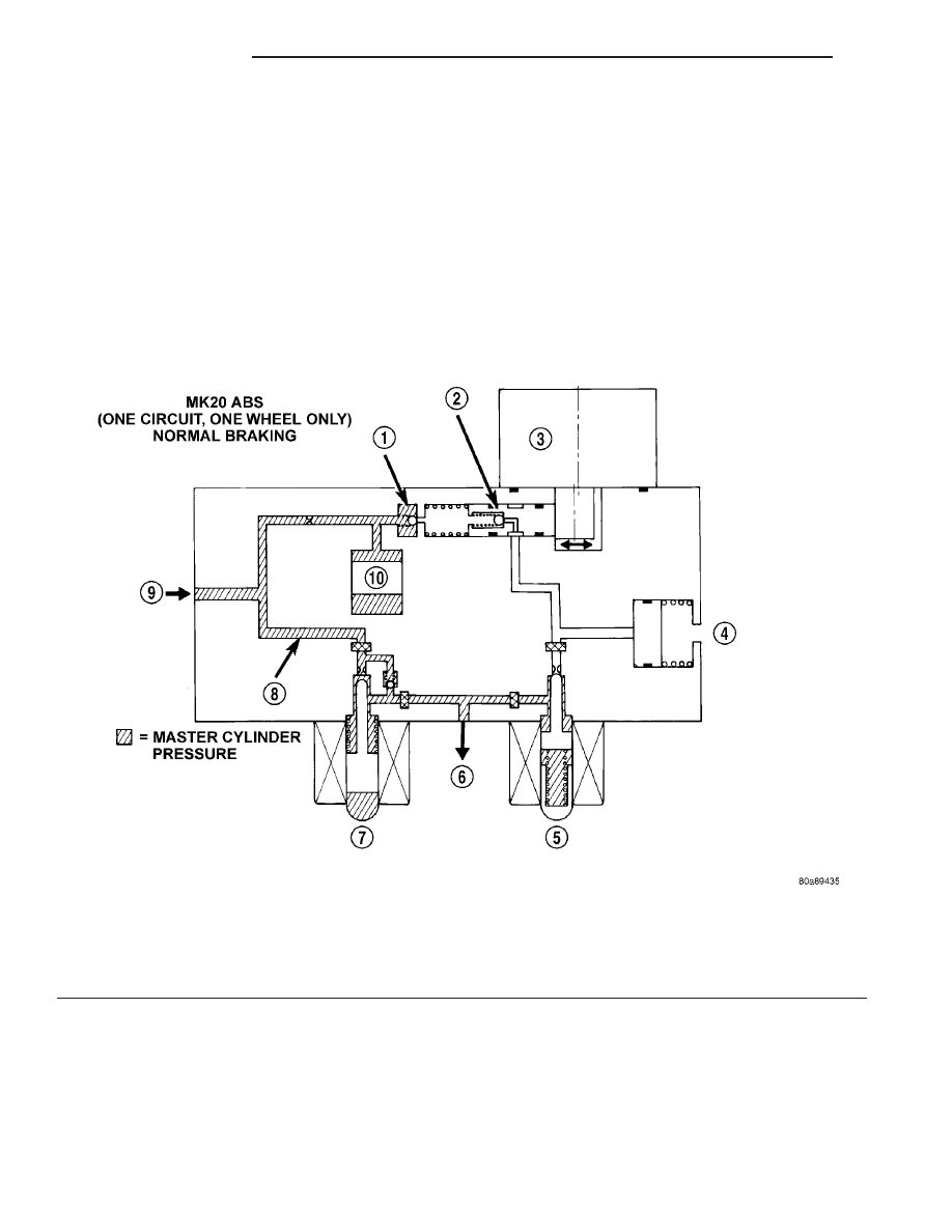
The hydraulic diagram (Fig. 4) shows the vehicle in

the normal braking mode of the base brake hydraulic
system. The diagram shows no wheel spin or slip
occurring relative to the speed of the vehicle. The
driver is applying the brake pedal which builds pres-
sure in the brake hydraulic system to engage the
brakes and stop the vehicle.

Fig. 4 Normal Braking Hydraulic Circuit

1 - OUTLET VALVE

6 - TO RIGHT FRONT WHEEL

2 - PUMP PISTON

7 - NORMALLY OPEN VALVE (OFF)

3 - PUMP MOTOR (OFF)

8 - MASTER CYLINDER PRESSURE

4 - LOW PRESSURE ACCUMULATOR

9 - FROM MASTER CYLINDER

5 - NORMALLY CLOSED VALVE (OFF)

10 - NOISE DAMPER CHAMBER

5 - 54

BRAKES - ABS

ZB

HCU (HYDRAULIC CONTROL UNIT) (Continued)

ABS HYDRAULIC CIRCUIT AND SOLENOID VALVE
FUNCTION

The hydraulic diagram (Fig. 5) shows the vehicle in

the ABS braking mode. The diagram shows one
wheel is slipping because the driver is attempting to
stop the vehicle at a faster rate than is allowed by
the surface on which the tires are riding.

• The normally open and normally closed valves

modulate (build/decay) the brake hydraulic pressure
as required.

• The pump/motor is switched on so that the

brake fluid from the low pressure accumulators is
returned to the master cylinder circuits.

• The brake fluid is routed to either the master

cylinder or the wheel brake depending on the posi-
tion of the normally open valve.

Fig. 5 ABS Mode Hydraulic Circuit

1 - OUTLET VALVE

8 - NORMALLY OPEN VALVE (MODULATING)

2 - PUMP PISTON

9 - FROM MASTER CYLINDER

3 - PUMP MOTOR (ON)

10 - MASTER CYLINDER PRESSURE

4 - LOW PRESSURE ACCUMULATOR PRESSURE

11 - CONTROLLED WHEEL PRESSURE

5 - LOW PRESSURE ACCUMULATOR

12 - PUMP INTERSTAGE PRESSURE

6 - NORMALLY CLOSED VALVE (MODULATING)

13 - NOISE DAMPER CHAMBER

7 - TO RIGHT FRONT WHEEL

ZB

BRAKES - ABS

5 - 55

HCU (HYDRAULIC CONTROL UNIT) (Continued)

ICU (INTEGRATED CONTROL
UNIT)

DESCRIPTION

The hydraulic control unit (HCU) and the control-

ler antilock brake (CAB) used with this antilock
brake system are combined (integrated) into one
unit, which is called the integrated control unit (ICU)
(Fig. 6). The ICU is located behind a panel, in front
of the left front tire and wheel assembly (Fig. 7).

The ICU consists of the following components: the

CAB, six (build/decay) solenoid valves (three inlet
valves and three outlet valves), valve block, fluid
accumulators, a pump, and an electric pump/motor.

The replaceable components of the ICU are the

HCU and the CAB. No attempt should be made to
service any components of the HCU or CAB.

For additional information on the CAB, (Refer to 8

-

ELECTRICAL/ELECTRONIC

CONTROL

MOD-

ULES/CONTROLLER

ANTILOCK

BRAKE

-

DESCRIPTION). For additional information on the
HCU, (Refer to 5 - BRAKES - ABS/HYDRAULIC/ME-
CHANICAL/HCU (HYDRAULIC CONTROL UNIT) -
DESCRIPTION).

OPERATION

For information of the ICU, refer to these individ-

ual components of the ICU:

• CONTROLLER ANTILOCK BRAKE (CAB)

(Refer to 8 - ELECTRICAL/ELECTRONIC CON-
TROL

MODULES/CONTROLLER

ANTILOCK

BRAKE - OPERATION)

• HYDRAULIC CONTROL UNIT (HCU) (Refer to

5 - BRAKES - ABS/HYDRAULIC/MECHANICAL/
HCU (HYDRAULIC CONTROL UNIT) - OPERA-
TION)

REMOVAL

NOTE: Before proceeding, review Warnings and
Cautions. (Refer to 5 - BRAKES - WARNING) (Refer
to 5 - BRAKES - CAUTION)

(1) Using a brake pedal holder, depress the brake

pedal past its first one inch of travel and hold it in
this position (Fig. 8). This will isolate the master cyl-
inder from the brake hydraulic system and will not
allow the brake fluid to drain out of the master cyl-
inder reservoir.

(2) Disconnect battery negative (-) terminal and

isolate cable.

(3) Raise vehicle. (Refer to LUBRICATION &

MAINTENANCE/HOISTING - STANDARD PROCE-
DURE)

(4) Remove left front tire and wheel assembly.

(Refer to 22 - TIRES/WHEELS - REMOVAL)

(5) Remove access panel in forward portion of left

front wheel well (Fig. 7).

(6) Remove belly pan front extension. (Refer to 23 -

BODY/EXTERIOR/BELLY PAN - REMOVAL)

(7) Pull outward on connector lock and disconnect

24-way connector at CAB.

(8) Remove three chassis brake tubes going to

brakes at ICU hydraulic control unit (Fig. 9).

(9) Remove primary and secondary brake tubes

coming from master cylinder at ICU hydraulic con-
trol unit (Fig. 9).

(10) Remove three bolts attaching ICU to mount-

ing bracket (Fig. 10).

(11) Remove ICU from vehicle.

Fig. 6 Integrated Control Unit (Typical)

1 - PUMP/MOTOR
2 - HCU
3 - PUMP/MOTOR CONNECTOR
4 - CAB

Fig. 7 ICU Location

1 - ICU
2 - LEFT FRONT TIRE AND WHEEL ASSEMBLY

5 - 56

BRAKES - ABS

ZB

(12) If CAB and HCU must be separated, (Refer to

5

-

BRAKES/HYDRAULIC/MECHANICAL/ICU

(INTEGRATED CONTROL UNIT) - DISASSEMBLY).

DISASSEMBLY

(1) Disconnect the pump/motor wiring harness

from the CAB (Fig. 11).

(2) Remove the 4 bolts attaching the CAB to the

HCU (Fig. 12).

(3) Remove the CAB from the HCU.

Fig. 8 Brake Pedal Holding Tool Installed

1 - CLUTCH PEDAL
2 - THROTTLE PEDAL
3 - BRAKE PEDAL HOLDING TOOL
4 - STEERING WHEEL
5 - DRIVER’S SEAT
6 - BRAKE PEDAL

Fig. 9 Brake Tubes At ICU

1 - PRIMARY BRAKE TUBE FROM MASTER CYLINDER
2 - CHASSIS BRAKE TUBE TO LEFT FRONT BRAKE
3 - SECONDARY BRAKE TUBE FROM MASTER CYLINDER
4 - CHASSIS BRAKE TUBE TO REAR BRAKES
5 - ICU
6 - CHASSIS BRAKE TUBE TO RIGHT FRONT BRAKE

Fig. 10 ICU Mounting

1 - FRAME MOUNTED BRACKET
2 - ISOLATOR
3 - MOUNTING BOLT
4 - ICU

Fig. 11 Pump/Motor To CAB Wiring Harness

(Typical)

1 - CAB
2 - PUMP MOTOR WIRING HARNESS
3 - PUMP MOTOR
4 - HCU VALVE BLOCK

ZB

BRAKES - ABS

5 - 57

ICU (INTEGRATED CONTROL UNIT) (Continued)


Content   ..  42  43  44  45   ..