Dodge Sprinter. Manual - part 239
 

  Index      Dodge     Dodge Sprinter / Mercedes-Benz - service repair manual 2006 year


Search            


Content   ..  237  238  239  240   ..


Dodge Sprinter. Manual - part 239


FRONT BUMPER - STEPS

REMOVAL

(1) Remove fascia. (Refer to 13 - FRAME &

BUMPERS/BUMPERS/FRONT

FASCIA

-

REMOVAL)

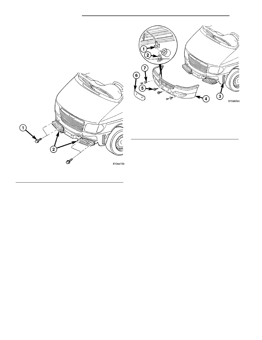
(2) Remove the bolts and remove the steps. (Fig.

1)

INSTALLATION

(1) Install step and bolts.
(2) Tighten bolts to 20 N·m (15 ft. lbs.).
(3) Install

fascia.

(Refer

to

13

-

FRAME

&

BUMPERS/BUMPERS/FRONT FASCIA - INSTAL-
LATION)

FRONT FASCIA

REMOVAL

(1) Remove the screws and cover. (Fig. 2)
(2) Remove push pin fasteners.
(3) Remove fascia screws.
(4) Pull bumper forward off support brackets.
(5) Disconnect electrical connector.

INSTALLATION

(1) Connect outside temperature sensor electrical

connector.

(2) Slide fascia onto the support brackets.
(3) Install fascia screws and tighten to 23 N·m (17

ft. lbs.).

(4) Install push pin fasteners.
(5) Install cover and screws.

REAR BUMPER - STEP

REMOVAL

(1) Remove rear fascia. (Refer to 13 - FRAME &

BUMPERS/BUMPERS/REAR FASCIA - REMOVAL)

(2) Remove frame bolts/nuts. (Fig. 3)
(3) Remove the remaining support bolts.

Fig. 1 BUMPER STEPS

1 - BOLTS (2 PER STEP)
2 - STEPS

Fig. 2 FRONT FASCIA

1 - ELECTRICAL CONNECTOR
2 - OUTSIDE TEMPERATURE SENSOR
3 - FASCIA SUPPORT BRACKET
4 - FASCIA
5 - SCREWS (2)
6 - COVER
7 - PUSH PIN FASTENERS

13 - 2

FRAME & BUMPERS

VA

INSTALLATION

(1) Install bumper step and install support bolts.
(2) Tighten bolts to 38 N·m (28 ft. lbs.).
(3) Install frame bolts/nuts and tighten to 90 N·m

(66 ft. lbs.).

(4) Install

fascia.

(Refer

to

13

-

FRAME

&

BUMPERS/BUMPERS/REAR FASCIA - INSTALLA-
TION)

REAR FASCIA

REMOVAL

(1) Remove screws and remove reflectors. (Fig. 4)
(2) Remove fascia bolts.
(3) Release bumper support brackets clips below

end panel.

(4) Press dowel pins out of and remove four plastic

rivets connecting fascia to rear step, if equipped.

(5) Separate the corners of the fascia from the sup-

port brackets and remove fascia.

INSTALLATION

(1) Install fascia and seat the corners over the sup-

port brackets.

(2) Seat bumper support brackets clips below end

panel firmly.

(3) Install the four plastic rivets to the bumper

step, if equipped.

(4) Install fascia bolts and tighten to 23 N·m (17

ft. lbs.).

(5) Install reflectors and reflector screws.

FRAME

SPECIFICATIONS

SPECIFICATIONS - FRAME DIMENSIONS

NOTE: Frame dimensions are listed in metric scale.

VEHICLE PREPARATION

Position the vehicle on a level work surface. Verti-

cal dimensions can be taken from the work surface to
the locations indicated were applicable.

Fig. 3 REAR BUMPER STEP

1 - FRAME BOLTS/NUTS (2)
2 - BOLTS (4)
3 - BUMPER STEP
4 - REAR FASCIA

Fig. 4 REAR FASCIA

1 - FASCIA
2 - BOLTS
3 - TAB
4 - REFLECTOR
5 - SUPPORT BRACKET

VA

FRAME & BUMPERS

13 - 3

INDEX

DESCRIPTION

FIGURE

05 FRAME DIMEN-

SIONS 1

5

05 FRAME DIMEN-

SIONS 2

6

FRAME DIMENSIONS

7

13 - 4

FRAME & BUMPERS

VA

Fig.

5

0

5

FRAME

DIMENSIONS

1

VA

FRAME & BUMPERS

13 - 5


Content   ..  237  238  239  240   ..