Dodge Ram Truck 1500-2500-3500. Manual - part 950
P0685-AUTO SHUTDOWN RELAY CONTROL CIRCUIT (CONTINUED)
For the Engine circuit diagram (Refer to 9 - ENGINE - SCHEMATICS AND DIAGRAMS).
For a complete wiring diagram Refer to Section 8W.
•
When Monitored:
With ignition on. Battery voltage above 10 volts.
•
Set Condition:
The actual ASD state is not equal to the desired ASD state. One Trip Fault. Three good trips to turn off the
MIL.
Possible Causes
INTERNAL FUSED B+ CIRCUITS
(K51) ASD RELAY CONTROL CIRCUIT OPEN
(K51) ASD RELAY CONTROL CIRCUIT SHORTED TO GROUND
ASD RELAY
PCM
Always perform the Pre-Diagnostic Troubleshooting procedure before proceeding. (Refer to 9 - ENGINE -
DIAGNOSIS AND TESTING).
Diagnostic Test
1.
ASD RELAY OPERATION
Ignition on, engine not running.
With a scan tool, actuate the ASD Relay.
Is the ASD Relay operating?
Yes
>> Refer to the INTERMITTENT CONDITION Diagnostic Procedure.
Perform the POWERTRAIN VERIFICATION TEST. (Refer to 9 - ENGINE - STANDARD PROCEDURE)
No
>> Go To 2
2.
INTERNAL FUSED B+ CIRCUITS
Turn the ignition off.
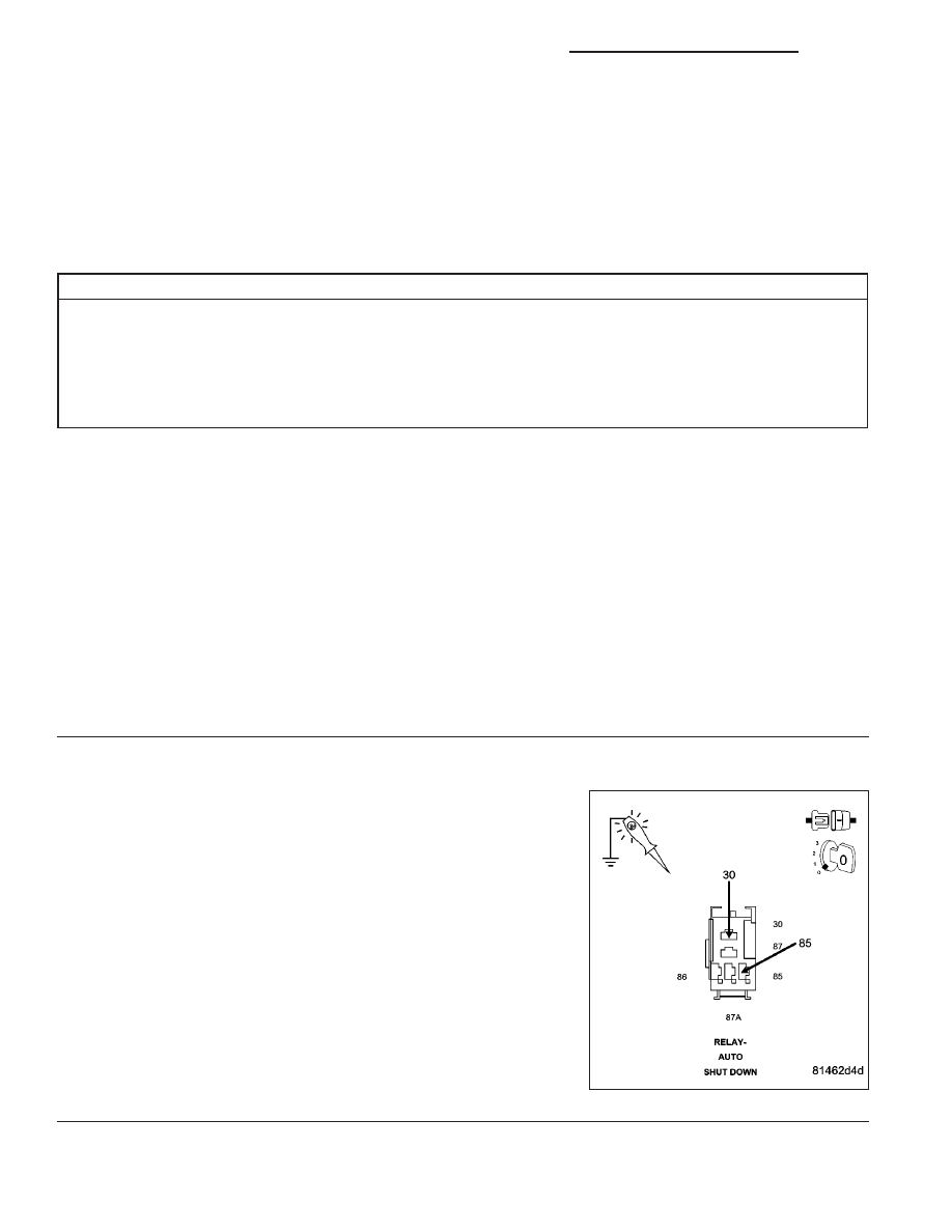
Remove the ASD Relay from the IPM.
Using a 12-volt test light connected to ground, probe the Internal
Fused B+ circuits in the IPM.
Does the test light illuminate brightly?
Yes
>> Go To 3
No
>> Repair the open or short to ground in the Internal Fused
B+ circuits. Inspect and replace any open fuses.
Perform the POWERTRAIN VERIFICATION TEST. (Refer
to 9 - ENGINE - STANDARD PROCEDURE)
9 - 722
ENGINE - ELECTRICAL DIAGNOSTICS - 3.7L/4.7L/5.7L
DR/DH