Dodge Ram Truck 1500-2500-3500. Manual - part 883
P0405-EGR POSITION SENSOR CIRCUIT LOW (CONTINUED)
For the Engine circuit diagram (Refer to 9 - ENGINE - SCHEMATICS AND DIAGRAMS).
For a complete wiring diagram Refer to Section 8W.
•
When Monitored:
With the ignition on. Battery voltage above 10.0 volts.
•
Set Condition:
EGR Position Sensor Signal is less than 0.1 of a volt. One trip Fault.
Possible Causes
(F856) 5-VOLT SUPPLY CIRCUIT SHORTED TO GROUND
(F856) 5-VOLT SUPPLY CIRCUIT OPEN
(K34) EGR POSITION SENSOR SIGNAL CIRCUIT SHORTED TO GROUND
(K34) EGR POSITION SENSOR SIGNAL CIRCUIT SHORTED TO THE (K900) SENSOR GROUND CIRCUIT
EGR POSITION SENSOR
PCM
Always perform the Pre-Diagnostic Troubleshooting procedure before proceeding. (Refer to 9 - ENGINE -
DIAGNOSIS AND TESTING).
Diagnostic Test
1.
EGR POSITION SENSOR BELOW 0.2 OF A VOLT
Ignition on, engine not running.
With a scan tool, read the EGR Position Sensor voltage.
Is the voltage below 0.2 of a volt?
Yes
>> Go To 2
No
>> Go To 9
2.
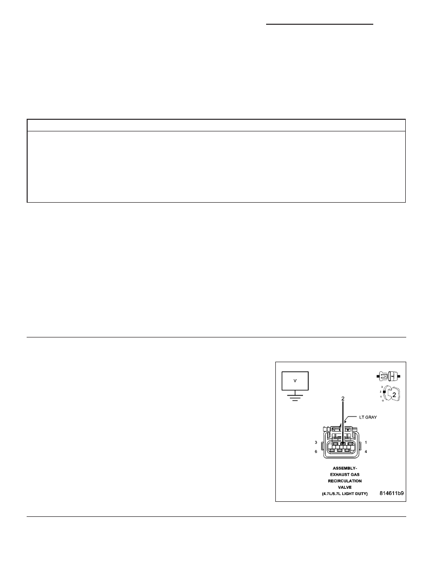
(F856) 5-VOLT SUPPLY CIRCUIT
Turn the ignition off.
Disconnect the EGR Solenoid harness connector.
Ignition on, engine not running.
Measure the voltage of the (F856) 5-volt Supply circuit in the EGR
Solenoid harness connector.
Is the voltage between 4.5 to 5.2 volts?
Yes
>> Go To 3
No
>> Go To 6
9 - 454
ENGINE - ELECTRICAL DIAGNOSTICS - 3.7L/4.7L/5.7L
DR/DH