Dodge Ram Truck 1500-2500-3500. Manual - part 871
 

  Index      Dodge     Dodge Ram Truck 1500-2500-3500 - service repair manual 2005 year


Search            


Content   ..  869  870  871  872   ..


Dodge Ram Truck 1500-2500-3500. Manual - part 871


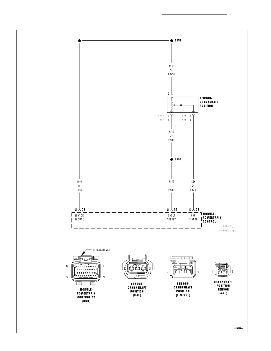
P0335-CRANKSHAFT POSITION SENSOR CIRCUIT

9 - 406

ENGINE - ELECTRICAL DIAGNOSTICS - 3.7L/4.7L/5.7L

DR/DH

P0335-CRANKSHAFT POSITION SENSOR CIRCUIT (CONTINUED)

For the Engine circuit diagram (Refer to 9 - ENGINE - SCHEMATICS AND DIAGRAMS).

For a complete wiring diagram Refer to Section 8W.

When Monitored:
Engine cranking.

Set Condition:
No CKP signal is present during engine cranking, and at least 8 camshaft position sensor signals have
occurred. One Trip Fault. Three good trips to turn off the MIL.

Possible Causes

(F855) 5-VOLT SUPPLY CIRCUIT SHORTED TO BATTERY VOLTAGE

(F855) 5-VOLT SUPPLY CIRCUIT OPEN

(F855) 5-VOLT SUPPLY CIRCUIT SHORTED TO GROUND

(K24) CKP SIGNAL CIRCUIT OPEN

(K24) CKP SIGNAL CIRCUIT SHORTED TO BATTERY VOLTAGE

(K24) CKP SIGNAL CIRCUIT SHORTED GROUND

(K24) CKP SIGNAL CIRCUIT SHORTED TO THE (F855) 5-VOLT SUPPLY CIRCUIT

(K900) SENSOR GROUND CIRCUIT OPEN

CRANKSHAFT POSITION SENSOR

CAMSHAFT POSITION SENSOR

PCM

Always perform the Pre-Diagnostic Troubleshooting procedure before proceeding. (Refer to 9 - ENGINE -
DIAGNOSIS AND TESTING).

Diagnostic Test

1.

ACTIVE DTC

Crank the engine.

Ignition on, engine not running.

With a scan tool, read DTCs.

Is the DTC active at this time?

Yes

>> Go To 2

No

>> Go To 14

DR/DH

ENGINE - ELECTRICAL DIAGNOSTICS - 3.7L/4.7L/5.7L

9 - 407

P0335-CRANKSHAFT POSITION SENSOR CIRCUIT (CONTINUED)

2.

(F855) 5-VOLT SUPPLY CIRCUIT

Turn the ignition off.

Disconnect the CKP Sensor harness connector.

Ignition on, engine not running.

Measure the voltage on the (F855) 5-volt Supply circuit in the CKP
Sensor harness connector.

Is the voltage between 4.5 and 5.2 volts?

Yes

>> Go To 3

No

>> Go To 10

3.

(K24) CKP SIGNAL CIRCUIT

Measure the voltage on the (K24) CKP Signal circuit in the CKP Sen-
sor harness connector.

Is the voltage between 4.5 and 5.0 volts?

Yes

>> Go To 4

No

>> Go To 7

9 - 408

ENGINE - ELECTRICAL DIAGNOSTICS - 3.7L/4.7L/5.7L

DR/DH

P0335-CRANKSHAFT POSITION SENSOR CIRCUIT (CONTINUED)

4.

(K900) SENSOR GROUND CIRCUIT OPEN

Turn the ignition off.

Disconnect the C2 PCM harness connector.

CAUTION: Do not probe the PCM harness connectors. Probing
the PCM harness connectors will damage the PCM terminals
resulting in poor terminal to pin connection. Install Miller Special
Tool #8815 to perform diagnosis.
Measure the resistance of the (K900) Sensor ground circuit from the
CKP Sensor harness connector to the appropriate terminal of special
tool #8815.

Is the resistance below 5.0 ohms?

Yes

>> Go To 5

No

>> Repair the open in the (K900) Sensor ground circuit.

Perform the POWERTRAIN VERIFICATION TEST. (Refer
to 9 - ENGINE - STANDARD PROCEDURE)

5.

(K24) CKP SIGNAL CIRCUIT SHORTED TO THE (F855) 5-VOLT SUPPLY CIRCUIT

Measure the resistance between the (K24) CKP Signal circuit and the
(F855) 5-volt Supply circuit in the CKP Sensor harness connector.

Is the resistance below 5.0 ohms?

Yes

>> Repair the short between the (K24) CKP Signal circuit and

the (F855) 5-volt Supply circuit.

Perform the POWERTRAIN VERIFICATION TEST. (Refer
to 9 - ENGINE - STANDARD PROCEDURE)

No

>> Go To 6

DR/DH

ENGINE - ELECTRICAL DIAGNOSTICS - 3.7L/4.7L/5.7L

9 - 409


Content   ..  869  870  871  872   ..