Dodge Ram Truck 1500-2500-3500. Manual - part 556
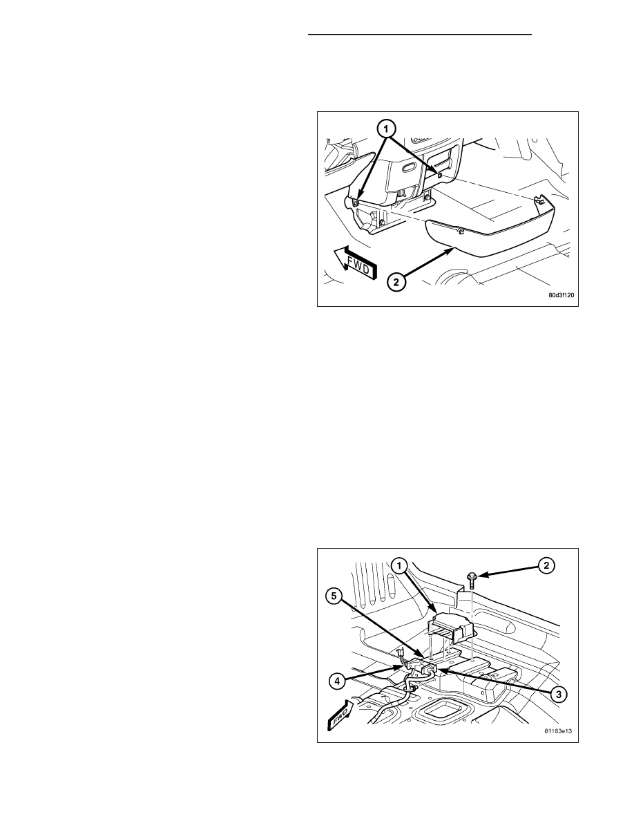
NOTE: The Airbag Control Module (ACM) cover is used only on models with an automatic transmission.
Models with a manual transmission require that the floor console be removed to access the ACM for ser-
vice. (Refer to 23 - BODY/INTERIOR/FLOOR CONSOLE - REMOVAL).
1. Disconnect and isolate the battery negative cable.
Wait two minutes for the system capacitor to dis-
charge before further service.
2. Using a trim stick or another suitable wide flat-
bladed tool, gently pry each side of the ACM cover
(2) away from the instrument panel at each side of
the center bracket on the floor panel transmission
tunnel far enough to disengage the two snap clip
retainers from the instrument panel receptacles (1).
3. Remove the ACM cover from the instrument panel.
INSTALLATION
MODULE
WARNING: To avoid personal injury or death, on vehicles equipped with airbags, disable the supplemental
restraint system before attempting any steering wheel, steering column, airbag, seat belt tensioner, impact
sensor, or instrument panel component diagnosis or service. Disconnect and isolate the battery negative
(ground) cable, then wait two minutes for the system capacitor to discharge before performing further diag-
nosis or service. This is the only sure way to disable the supplemental restraint system. Failure to take the
proper precautions could result in accidental airbag deployment.
WARNING: To avoid personal injury or death, never strike or drop the airbag control module, as it can dam-
age the impact sensor or affect its calibration. The airbag control module contains the impact sensor, which
enables the system to deploy the supplemental restraints. If an airbag control module is accidentally
dropped during service, the module must be scrapped and replaced with a new unit. Failure to observe this
warning could result in accidental, incomplete, or improper supplemental restraint deployment.
1. Position the Airbag Control Module (ACM) (1) to
the left side of the floor panel transmission tunnel
near the ACM bracket (5). When the ACM is cor-
rectly positioned, the arrow on the ACM label will
be pointed forward in the vehicle.
2. From the left side of the floor panel transmission
tunnel, slide the ACM toward the right far enough
to engage the slotted hole in the right ACM mount-
ing flange under the head of the previously loos-
ened right mounting screw (2), then engage the
locating pin on the bottom of the left ACM mounting
flange into the locating hole in the bracket.
3. Still working from the left side of the floor panel
transmission tunnel, install and tighten the two
screws that secure the left ACM mounting flanges
to the bracket that is welded onto the floor panel
transmission tunnel. Tighten the screws to 12 N·m (9 ft. lbs.).
8O - 258
RESTRAINTS - SERVICE INFORMATION
DR/DH