Dodge Ram Truck 1500-2500-3500. Manual - part 372
IGNITION UNLOCK CIRCUIT RATIONALITY CHECK
For the Instrument Cluster circuit diagram (Refer to 8 - ELECTRICAL/INSTRUMENT CLUSTER - SCHEMATICS
AND DIAGRAMS).
For a complete wiring diagram Refer to Section 8W.
•
When Monitored:
Continuously.
•
Set Condition:
One second of Run/Start above 5 Volts, Unlock Status Low, and Run/ACC Status High.
Possible Causes
IGNITION UNLOCK-RUN-START FUSE OPEN
(F21) IGNITION UNLOCK-RUN-START CIRCUIT OPEN
INSTRUMENT CLUSTER
Diagnostic Test
1.
IGNITION UNLOCK-RUN-START FUSE OPEN
Turn the ignition off.
Inspect the Ignition Unlock-Run-Start fuse in the PDC.
Is the fuse open?
Yes
>> Using the wiring diagram/schematic as a guide, inspect the wiring and connectors for a short to ground
condition.
Perform BODY VERIFICATION TEST - VER 1. (Refer to BODY VERIFICATION TEST - VER 1.)
No
>> Go To 2
2.
INSTRUMENT CLUSTER
Turn the ignition off.
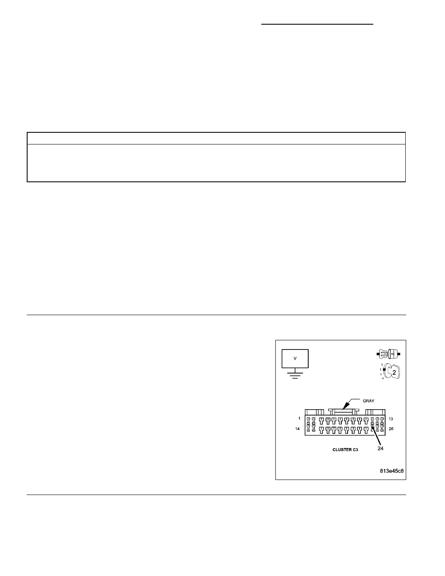
Disconnect the Instrument Cluster C3 harness connector.
Turn the ignition on.
Measure the voltage of the (F1) Ignition Unlock-Run-Start circuit.
Is the voltage above 10 volts?
Yes
>> Replace the Instrument Cluster in accordance with the ser-
vice information.
Perform BODY VERIFICATION TEST - VER 1. (Refer to
BODY VERIFICATION TEST - VER 1.)
No
>> Repair the (F1) Ignition Unlock-Run-Start circuit for an
open.
Perform BODY VERIFICATION TEST - VER 1. (Refer to
BODY VERIFICATION TEST - VER 1.)
8J - 48
INSTRUMENT CLUSTER - ELECTRICAL DIAGNOSTICS
DR/DH