Dodge Ram Truck 1500-2500-3500. Manual - part 371
BTSI OUTPUT CIRCUIT SHORTED OR OPEN (CONTINUED)
For the Instrument Cluster circuit diagram (Refer to 8 - ELECTRICAL/INSTRUMENT CLUSTER - SCHEMATICS
AND DIAGRAMS).
For a complete wiring diagram Refer to Section 8W.
•
When Monitored:
With the ignition in the Unlock or On position and the operator’s foot applied to the brake pedal. (Customer
Complaint: Vehicle can be shifted out of Park without pressing the brake pedal.)
•
Set Condition:
The Instrument Cluster detects a
9
0
9
or low value on the input circuit for the BTSI when ON.
Possible Causes
(Z101) BTSI SOLENOID GROUND CIRCUIT OPEN
(K32) BTSI SOLENOID CONTROL CIRCUIT SHORTED TO THE (Z101) BTSI SOLENOID GROUND CIRCUIT
(K32) BTSI SOLENOID CONTROL CIRCUIT SHORT TO GROUND
(K32) BTSI SOLENOID CONTROL CIRCUIT OPEN
BTSI SOLENOID
INSTRUMENT CLUSTER
Diagnostic Test
1.
TCM DTC PRESENT
Turn the ignition on.
With the DRBIII
T
, read DTCs.
Does the DRBIII
T
display any TCM DTCs?
Yes
>> Refer to Transmission for the related symptom(s).
Perform BODY VERIFICATION TEST - VER 1. (Refer to BODY VERIFICATION TEST - VER 1.)
No
>> Go To 2
2.
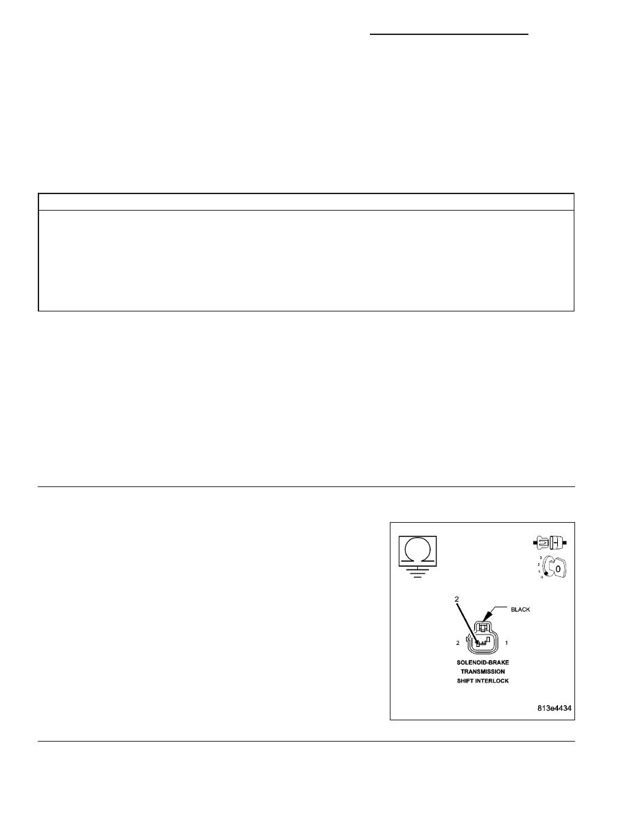
CHECK THE (Z101) BTSI SOLENOID GROUND CIRCUIT FOR AN OPEN
Turn the ignition off.
Disconnect the BTSI Solenoid harness connector.
Measure the resistance between ground and the (Z101) BTSI Solenoid
Ground circuit.
Is the resistance above 5.0 ohms?
Yes
>> Repair the (Z101) BTSI Solenoid Ground circuit for an
open.
Perform BODY VERIFICATION TEST - VER 1. (Refer to
BODY VERIFICATION TEST - VER 1.)
No
>> Go To 3
8J - 44
INSTRUMENT CLUSTER - ELECTRICAL DIAGNOSTICS
DR/DH