Dodge Ram Truck 1500-2500-3500. Manual - part 325
BATTERY CABLES
DESCRIPTION
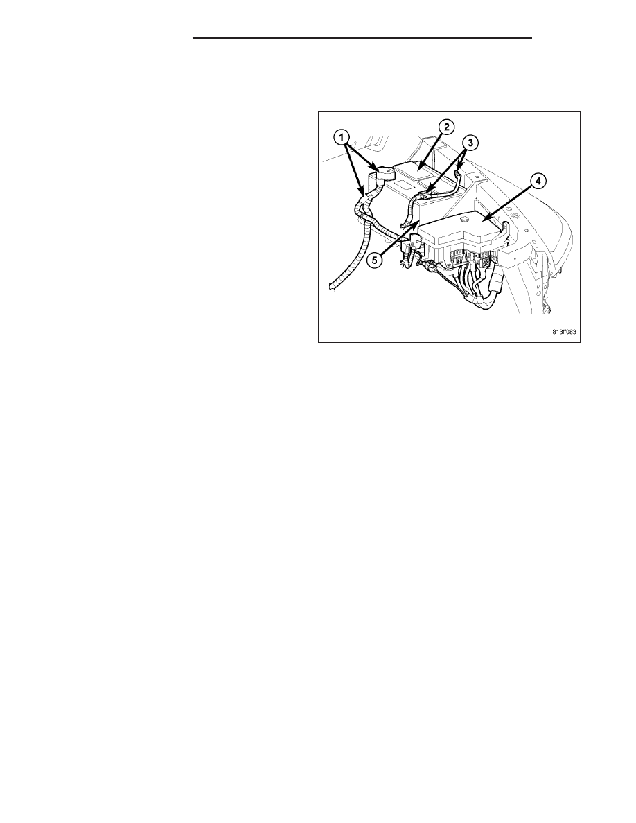
The battery cables (1) and (3) are large gauge,
stranded copper wires sheathed within a heavy plastic
or synthetic rubber insulating jacket. The wire used in
the battery cables combines excellent flexibility and
reliability with high electrical current carrying capacity.
The battery cables feature a stamped brass clamping
type female battery terminal crimped onto one end of
the battery cable wire and then solder-dipped. A
square headed pinch-bolt and hex nut are installed at
the open end of the female battery terminal clamp.
Large eyelet type terminals are crimped onto the
opposite end of the battery cable wire and then sol-
der-dipped. The battery positive cable wires (1) have a
red insulating jacket to provide visual identification and
feature a larger female battery terminal clamp to allow
connection to the larger battery positive terminal post.
The battery negative cable wires (3) have a black
insulating jacket and a smaller female battery terminal
clamp.
The battery cables cannot be repaired and, if dam-
aged or inoperative they must be replaced. Both the battery positive and negative cables are available for service
replacement. Refer to the appropriate wiring information for the location of the proper battery cable wire
harness diagrams. The wiring information also includes proper wire and connector repair procedures, further
details on wire harness routing and retention, as well as pin-out and location views for the various wire harness
connectors, splices and grounds.
OPERATION
The battery cables connect the battery terminal posts to the vehicle electrical system. These cables also provide a
path back to the battery for electrical current generated by the charging system for restoring the voltage potential of
the battery. The female battery terminal clamps on the ends of the battery cable wires provide a strong and reliable
connection of the battery cable to the battery terminal posts. The terminal pinch bolts allow the female terminal
clamps to be tightened around the male terminal posts on the top of the battery. The eyelet terminals secured to the
opposite ends of the battery cable wires provide secure and reliable connection of the battery cables to the vehicle
electrical system.
DIAGNOSIS AND TESTING - BATTERY CABLES
A voltage drop test will determine if there is excessive resistance in the battery cable terminal connections or the
battery cables. If excessive resistance is found in the battery cable connections, the connection point should be
disassembled, cleaned of all corrosion or foreign material, then reassembled. Following reassembly, check the volt-
age drop for the battery cable connection and the battery cable again to confirm repair.
When performing the voltage drop test, it is important to remember that the voltage drop is giving an indication of
the resistance between the two points at which the voltmeter probes are attached. EXAMPLE: When testing the
resistance of the battery positive cable, touch the voltmeter leads to the battery positive cable terminal clamp and to
the battery positive cable eyelet terminal at the starter solenoid B(+) terminal stud. If you probe the battery positive
terminal post and the battery positive cable eyelet terminal at the starter solenoid B(+) terminal stud, you are read-
ing the combined voltage drop in the battery positive cable terminal clamp-to-terminal post connection and the bat-
tery positive cable.
8F - 20
BATTERY SYSTEM
DR/DH