Dodge Ram Truck 1500-2500-3500. Manual - part 299
*NO RESPONSE FROM PCM (PCI BUS) - NGC (CONTINUED)
2.
(D25) PCI BUS CIRCUIT OPEN
With the DRB, read PCM DTC’s. This is to ensure power and ground
to the PCM are operational.
NOTE: If the DRB will not read PCM DTC’s, follow the NO
RESPONSE TO PCM (SCI ONLY) - NGC symptom.
NOTE: If the vehicle will not start and the DRB displays a no
response message, refer to the appropriate symptom in the
Engine Electrical Diagnostics category.
Turn the ignition off.
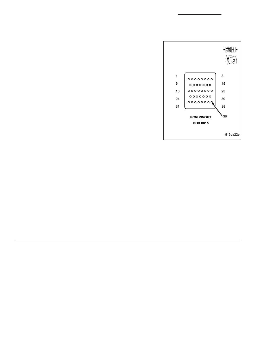
Disconnect the PCM C1 harness connector.
CAUTION: Do not probe the PCM harness connectors. Probing
the PCM harness connectors will damage the PCM terminals
resulting in poor terminal to pin connection. Install Miller Special
Tool #8815 to perform diagnosis.
Use Scope input cable CH7058, Cable to Probe adapter CH7062, and
the red and black test probes.
Connect the scope input cable to the channel one connector on the
DRB. Attach the red and black leads and the cable to probe adapter to
the scope input cable.
With the DRBIII
T
select Pep Module Tools.
Select lab scope.
Select Live Data.
Select 12 volt square wave.
Press F2 for Scope.
Press F2 and use the down arrow to set voltage range to 20 volts. Press F2 again when complete.
Connect the Black lead to the chassis ground. Connect the Red lead to the PCI Bus circuit in the appropriate ter-
minal of special tool #8815.
Turn the ignition on.
Observe the voltage display on the DRB Lab Scope.
Does the voltage pulse from 0 to approximately 7.5 volts?
Yes
>> Replace the Powertrain Control Module in accordance with the service information.
Perform (NGC) POWERTRAIN VERIFICATION TEST - VER 1.
No
>> Repair the (D25) PCI Bus circuit for an open.
Perform (NGC) POWERTRAIN VERIFICATION TEST - VER 1.
8E - 68
ELECTRONIC CONTROL MODULES - ELECTRICAL DIAGNOSTICS
DR/DH