Dodge Ram Truck 1500-2500-3500. Manual - part 279
 

  Index      Dodge     Dodge Ram Truck 1500-2500-3500 - service repair manual 2005 year


Search            


Content   ..  277  278  279  280   ..


Dodge Ram Truck 1500-2500-3500. Manual - part 279


*KEY IN IGNITION AND DRIVER’S DOOR OPEN CHIME INOPERATIVE (CONTINUED)

For the Chime system circuit diagram (Refer to 8 - ELECTRICAL/CHIME/BUZZER - SCHEMATICS AND DIA-
GRAMS)

For a complete wiring diagram Refer to Section 8W.

Possible Causes

(Z42) GROUND OPEN

(G26) KEY-IN IGNITION SWITCH OPEN

IGNITION SWITCH

CLUSTER

Diagnostic Test

1.

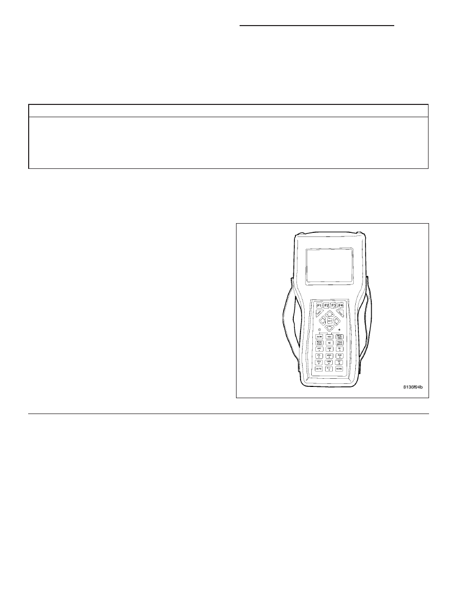
READ KEY-IN IGNITION SWITCH STATUS ON DRBIII

NOTE: The driver’s door ajar switch must be oper-
ational for the result of this test to be valid.
Ensure that the Key is still in the Ignition Switch.

With the DRBIII

T

select: Electro/Mech Cluster, Input

Output.

Read the Key-In Ign Sw.

Does the DRBIII

T

show Key-In Ign CLOSED?

Yes

>> Replace and program the Cluster in accor-

dance with the Service Information.

Perform BODY VERIFICATION TEST -
VER 1 (Refer to BODY VERIFICATION
TEST - VER 1).

No

>> Go To 2

8B - 6

CHIME/BUZZER - ELECTRICAL DIAGNOSTICS

DR/DH

*KEY IN IGNITION AND DRIVER’S DOOR OPEN CHIME INOPERATIVE (CONTINUED)

2.

IGNITION SWITCH GROUND CIRCUIT OPEN

Turn the ignition off.

Disconnect the Ignition Switch connector.

Turn all lights off.

Measure the resistance between ground and the (Z42) Ground circuit
in the ignition switch harness connector.

Is the resistance below 5.0 ohms?

Yes

>> Go To 3

No

>> Repair the (Z42) Ground circuit for an open.

Perform BODY VERIFICATION TEST - VER 1 (Refer to
BODY VERIFICATION TEST - VER 1).

3.

IGNITION SWITCH OPEN

Connect the ignition switch connector if disconnected.

Turn ignition on.

With the ignition switch connector connected, back jumper the (G26)
Key-In Ignition Switch Sense circuit to ground at the ignition switch
connector.

With the DRBIII

T

, enter Instrument Cluster Input/Outputs and observe

the Key-In Ign Sw status.

Does the DRBIII display Key-In Ign SW: Closed?

Yes

>> Replace the Ignition Switch.

Perform BODY VERIFICATION TEST - VER 1 (Refer to
BODY VERIFICATION TEST - VER 1).

No

>> Go To 4

DR/DH

CHIME/BUZZER - ELECTRICAL DIAGNOSTICS

8B - 7

*KEY IN IGNITION AND DRIVER’S DOOR OPEN CHIME INOPERATIVE (CONTINUED)

4.

KEY-IN IGNITION SWITCH SENSE CIRCUIT OPEN

Turn the ignition off.

Disconnect the Ignition Switch harness connector.

Disconnect the Cluster C3 harness connector.

Measure the resistance of the (G26) Key-In Ignition Switch Sense cir-
cuit between the ignition switch connector and the Instrument Cluster
C3 connector.

Is the resistance below 5.0 ohms?

Yes

>> Replace and program the Instrument Cluster in accor-

dance with the Service Information.

Perform BODY VERIFICATION TEST - VER 1 (Refer to
BODY VERIFICATION TEST - VER 1).

No

>> Repair the (G26) Key-In Ignition Switch Sense circuit for

an open

Perform BODY VERIFICATION TEST - VER 1 (Refer to
BODY VERIFICATION TEST - VER 1).

8B - 8

CHIME/BUZZER - ELECTRICAL DIAGNOSTICS

DR/DH

*CHIME INOPERATIVE

For the Chime system circuit diagram (Refer to 8 - ELECTRICAL/CHIME/BUZZER - SCHEMATICS AND DIA-
GRAMS)

For a complete wiring diagram Refer to Section 8W.

Possible Causes

CLUSTER

Diagnostic Test

1.

ACTUATE THE CHIME WITH THE DRBIII

Turn the ignition on.

Close the doors.

With the DRBIII

T

select: Electro/Mech Cluster and

actuate the Chime.

Does the chime sound when actuated by the
DRBIII

T

?

Yes

>> If the chime operates as it should, check

for other reasons that the chime is being
inoperative.

Perform BODY VERIFICATION TEST -
VER 1 (Refer to BODY VERIFICATION
TEST - VER 1).

No

>> Replace and program the Cluster in accor-

dance with the Service Information.

Perform BODY VERIFICATION TEST -
VER 1 (Refer to BODY VERIFICATION
TEST - VER 1).

DR/DH

CHIME/BUZZER - ELECTRICAL DIAGNOSTICS

8B - 9


Content   ..  277  278  279  280   ..