Dodge Ram Truck 1500-2500-3500. Manual - part 206
NOTE: If diagnosis indicates that an internal malfunction has occurred, the aluminum body section must be
replaced as an assembly.
OPERATION
The master cylinder bore contains a primary and secondary piston. The primary piston supplies hydraulic pressure
to the front brakes. The secondary piston supplies hydraulic pressure to the rear brakes.
DIAGNOSIS AND TESTING
MASTER CYLINDER/POWER BOOSTER
1. Start engine and check booster vacuum hose connections. A hissing noise indicates vacuum leak. Correct any
vacuum leak before proceeding.
2. Stop engine and shift transmission into Neutral.
3. Pump brake pedal until all vacuum reserve in booster is depleted.
4. Press and hold brake pedal under light foot pressure. The pedal should hold firm, if the pedal falls away master
cylinder is faulty (internal leakage).
5. Start engine and note pedal action. It should fall away slightly under light foot pressure then hold firm. If no pedal
action is discernible, power booster, vacuum supply, or vacuum check valve is faulty. Proceed to the POWER
BOOSTER VACUUM TEST.
6. If the POWER BOOSTER VACUUM TEST passes, rebuild booster vacuum reserve as follows: Release brake
pedal. Increase engine speed to 1500 rpm, close the throttle and immediately turn off ignition to stop engine.
7. Wait a minimum of 90 seconds and try brake action again. Booster should provide two or more vacuum assisted
pedal applications. If vacuum assist is not provided, booster is faulty.
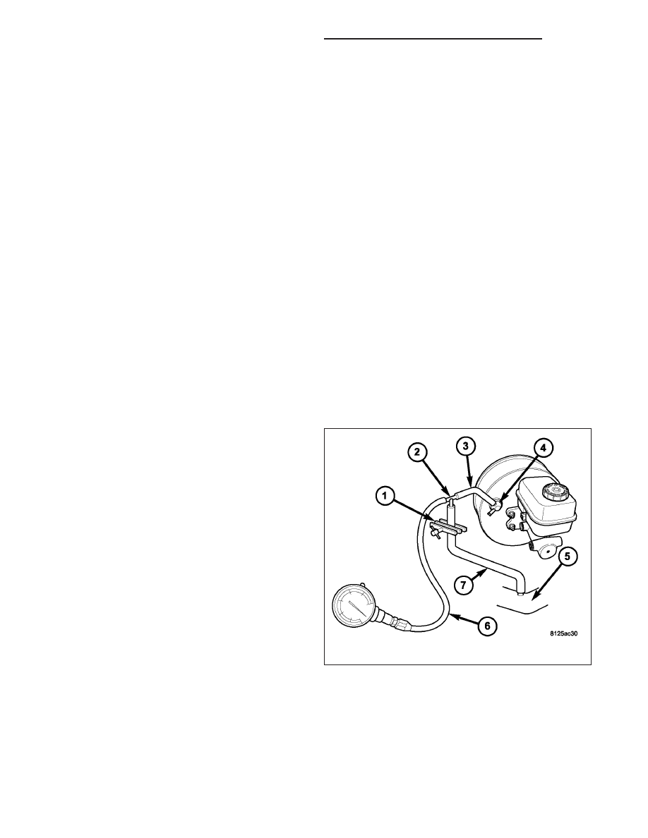
POWER BOOSTER VACUUM TEST
1. Connect vacuum gauge (6) to booster check valve
(4) with short length of hose (3) and T-fitting (2).
2. Start and run engine at curb idle speed for one
minute.
3. Observe the vacuum supply. If vacuum supply is
not adequate, repair vacuum supply.
4. Clamp (1) hose (7) shut between intake vacuum
source (5) and check valve (4).
5. Stop engine and observe vacuum gauge (6).
6. If vacuum drops more than one inch HG (33 milli-
bars) within 15 seconds, booster diaphragm or
check valve is faulty.
5 - 252
BRAKES - BASE - SERVICE INFORMATION
DR/DH