Dodge Ram Truck 1500-2500-3500. Manual - part 1905


  Index      Dodge     Dodge Ram Truck 1500-2500-3500 - service repair manual 2005 year


Search            


Content   ..  1903  1904  1905  1906   ..


Dodge Ram Truck 1500-2500-3500. Manual - part 1905
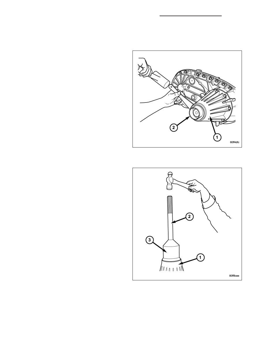


BOOT-EXTENSION HOUSING SEAL AND DUST

REMOVAL

1. Raise and support vehicle.

2. Remove rear propeller shaft. (Refer to 3 - DIFFER-

ENTIAL & DRIVELINE/PROPELLER SHAFT/PRO-
PELLER SHAFT - REMOVAL)

3. Use a suitable chisel or pry tool to remove the rear

extension housing dust boot (2).

4. Use a suitable chisel or pry tool to remove the rear

extension housing seal.

INSTALLATION

1. Clean fluid residue from sealing surface and

inspect for defects.

2. Install the extension housing dust boot and seal

assembly with Installer 9037 (3) and Handle
C-4171 (2).

3. Install propeller shaft. (Refer to 3 - DIFFERENTIAL

& DRIVELINE/PROPELLER SHAFT/PROPELLER
SHAFT - INSTALLATION)

4. Verify proper transfer case fluid level.

5. Lower vehicle.

21 - 1552

TRANSFER CASE - NV273 - SERVICE INFORMATION

DR/DH

FLUID

STANDARD PROCEDURE - FLUID DRAIN AND REFILL

The fill (1) and drain (2) plugs are both in the rear
case.

1. Raise vehicle.

2. Position drain pan under transfer case.

NOTE: It may be necessary to remove the exhaust
y-pipe at the exhaust manifold to properly access
the fill and drain plugs. Lowering the exhaust will
allow the plugs to be accessed for torquing during
installation. (Refer to 11 - EXHAUST SYSTEM/EX-
HAUST PIPE - REMOVAL)

3. Remove drain and fill plugs and drain lubricant

completely.

4. Install drain plug. Tighten plug to 41-54 N·m (30-40

ft. lbs.).

5. Remove drain pan.

6. Fill transfer case to bottom edge of fill plug opening

with Mopar

T

ATF +4, Automatic Transmission fluid.

7. Install and tighten fill plug to 41-54 N·m (30-40 ft. lbs.).

8. Install the exhaust y-pipe to the exhaust manifold, if removed. (Refer to 11 - EXHAUST SYSTEM/EXHAUST

PIPE - INSTALLATION)

9. Wipe any excess fluid that may have spilled onto the exhaust.

10. Lower vehicle.

SEAL-FRONT OUTPUT SHAFT

REMOVAL

1. Remove the front propeller shaft (Refer to 3 - DIF-

FERENTIAL & DRIVELINE/PROPELLER SHAFT/
PROPELLER SHAFT - REMOVAL).

2. Install two bolts 180° apart into the front output

shaft companion flange.

3. Place Holder 6719 (1) over the bolts (2) and

against the companion flange.

4. Remove and discard the front companion flange

nut.

5. Remove the companion flange from the front out-

put shaft. It may be necessary to use Flange puller
8992 to remove the companion flange.

6. Using a screw and a slide hammer, remove the

front output shaft seal.

DR/DH

TRANSFER CASE - NV273 - SERVICE INFORMATION

21 - 1553

INSTALLATION

1. Install the new front output shaft seal with Installer

MB991168A.

2. Install the front companion flange onto the front

output shaft.

3. Install two bolts 180° apart into the front output

shaft companion flange.

4. Place Holder 6719 (1) over the bolts (2) and

against the companion flange.

5. Install a new front companion flange nut. Tighten

the companion flange nut to 258-312 N·m (190-230
ft.lbs.).

6. Install front propeller shaft (Refer to 3 - DIFFEREN-

TIAL &

DRIVELINE/PROPELLER

SHAFT/PRO-

PELLER SHAFT - INSTALLATION).

SENSOR-MODE

DESCRIPTION

The transfer case mode sensor (1) is an electronic
device whose output can be interpreted to indicate the
shift motor shaft’s rotary position. The sensor consists
of a magnetic ring and four Hall Effect Transistors to
create a 4 channel digital device (non-contacting)
whose output converts the motor shaft position into a
coded signal. The TCCM must supply 5VDC (+/- 0.5v)
to the sensor and monitor the shift motor position. The
four channels are denoted A, B, C, and D. The sensor
is mechanically linked to the shaft of the cam which
causes the transfer case shifting. The mode sensor
draws less than 53 mA.

OPERATION

During normal vehicle operation, the Transfer Case Control Module (TCCM) monitors the mode sensor outputs at
least every 250 (+/-50) milliseconds when the shift motor is stationary and 400 microseconds when the shift motor
is active. A mode sensor signal between 3.8 Volts and 0.8 Volts is considered to be undefined.

Refer to SECTOR ANGLES vs. TRANSFER CASE POSITION for the relative angles of the transfer case shift sector
versus the interpreted transfer case gear operating mode. Refer to MODE SENSOR CHANNEL STATES for the
sensor codes returned to the TCCM for each transfer case mode sensor position. The various between gears posi-
tions can also be referred as the transfer case’s coarse position. These coarse positions come into play during shift
attempts.

21 - 1554

TRANSFER CASE - NV273 - SERVICE INFORMATION

DR/DH

SECTOR ANGLES vs. TRANSFER CASE POSITION

Shaft Angle (Degrees)

Transfer Case Position

+40

4LO

+20

N

0

2WD/AWD

-20

4HI

MODE SENSOR CHANNEL STATES

Transfer Case

Angle (degrees)

Sensor Channel A

Sensor Channel B

Sensor Channel C

Sensor Channel D

Between Gears

H

H

L

H

+40 (4LO)

H

H

L

L

Between Gears

H

H

L

H

Between Gears

H

L

L

H

+20 (NEUTRAL)

H

L

L

L

Between Gears

H

L

L

H

Between Gears

H

L

H

H

0 (2WD/AWD)

H

L

H

L

Between Gears

H

L

H

H

Between Gears

L

L

H

H

-20 (4HI)

L

L

H

L

Between Gears

L

L

H

H

Between Gears

L

H

H

H

SWITCH-SELECTOR

DESCRIPTION

The selector switch assembly (1) is mounted in the left
side of the vehicle’s Instrument Panel (IP) and con-
sists of a rotary knob connected to a resistive network
for the mode and range shift selections. Also located
in this assembly is a recessed, normally open momen-
tary switch for making shifts into and out of transfer
case NEUTRAL. A pen, or similar instrument, is used
to make a NEUTRAL shift selection, thus reducing the
likelihood of an inadvertent shift request.

The selector switch also contains four light emitting
diode’s (LED’s) to indicate the transfer case position
and whether a shift is in progress.

DR/DH

TRANSFER CASE - NV273 - SERVICE INFORMATION

21 - 1555


Content   ..  1903  1904  1905  1906   ..