Dodge Ram Truck 1500-2500-3500. Manual - part 1847


  Index      Dodge     Dodge Ram Truck 1500-2500-3500 - service repair manual 2005 year


Search            


Content   ..  1845  1846  1847  1848   ..


Dodge Ram Truck 1500-2500-3500. Manual - part 1847
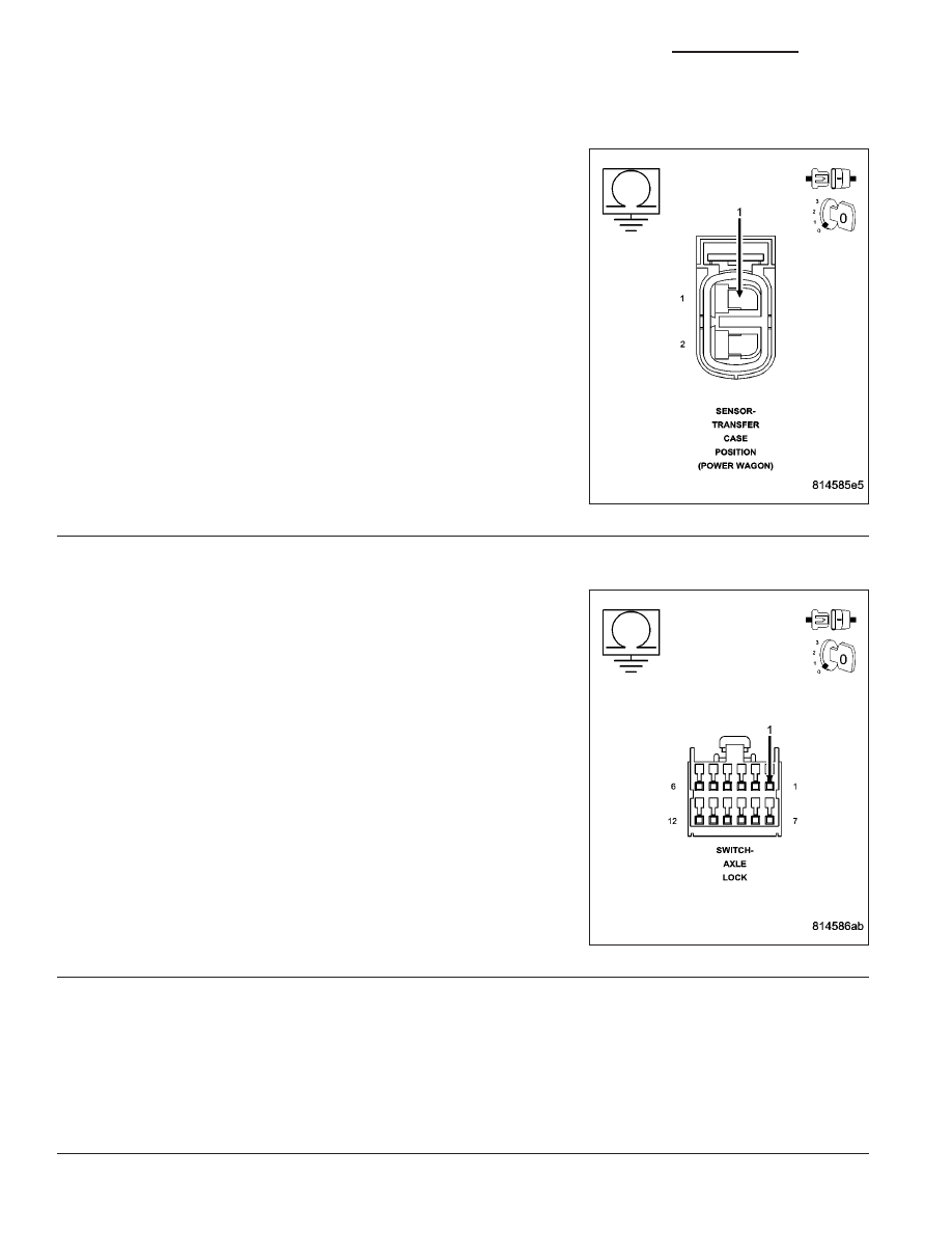


C2122–T-CASE/DIFFERENTIAL SWITCH SUPPLY VOLTAGE CIRCUIT LOW (CONTINUED)

4.

(K77) TRANSFER CASE POSITION SENSE CIRCUIT SHORT TO GROUND

Turn the ignition off.

Disconnect the Final Drive Control Module harness connector.

Measure the resistance between the (K77) Transfer Case Position
Sense circuit at the Transfer Case Position Sensor harness connector
and ground.

Is the resistance below 5.0 ohms?

Yes

>> Repair the (K77) Transfer Case Position Sense circuit for

a short to ground.

Perform the FDCM VERIFICATION TEST. (Refer to 3 -
DIFFERENTIAL & DRIVELINE - DIAGNOSIS AND TEST-
ING)

No

>> Go to 5

5.

(T537) LOCKER SWITCH SUPPLY CIRCUIT SHORT TO GROUND

Measure the resistance between the (T537) Locker Switch Supply cir-
cuit at the Axle Lock Switch harness connector and ground.

Is the resistance below 5.0 ohms?

Yes

>> Repair the (T537) Locker Switch Supply circuit for a short

to ground.

Perform the FDCM VERIFICATION TEST. (Refer to 3 -
DIFFERENTIAL & DRIVELINE - DIAGNOSIS AND TEST-
ING)

No

>> Go to 6

6.

FINAL DRIVE CONTROL MODULE

View repair.

Repair

Replace the Final Drive Control Module in accordance with the Service information.

Perform the FDCM VERIFICATION TEST. (Refer to 3 - DIFFERENTIAL & DRIVELINE - DIAGNOSIS
AND TESTING)

21 - 1320

TRANSFER CASE - ELECTRICAL DIAGNOSTICS (POWER WAGON)

DR/DH

C2122–T-CASE/DIFFERENTIAL SWITCH SUPPLY VOLTAGE CIRCUIT LOW (CONTINUED)

7.

INTERMITTENT WIRING AND CONNECTORS

The conditions necessary to set this DTC are not present at this time.

Using the wiring diagram/schematic as a guide, inspect the wiring and connectors.

While monitoring the scan tool data relative to this circuit, wiggle test the wiring and connectors.

Look for the data to change or for the DTC to reset during the wiggle test.

Were any problems found?

Yes

>> Repair as necessary.

Perform the FDCM VERIFICATION TEST. (Refer to 3 - DIFFERENTIAL & DRIVELINE - DIAGNOSIS
AND TESTING)

No

>> Test complete.

DR/DH

TRANSFER CASE - ELECTRICAL DIAGNOSTICS (POWER WAGON)

21 - 1321

C2123–T-CASE/DIFFERENTIAL SWITCH SUPPLY VOLTAGE CIRCUIT HIGH

21 - 1322

TRANSFER CASE - ELECTRICAL DIAGNOSTICS (POWER WAGON)

DR/DH

C2123–T-CASE/DIFFERENTIAL SWITCH SUPPLY VOLTAGE CIRCUIT HIGH (CONTINUED)

For a complete wiring diagram Refer to Section 8W

When Monitored:
With the ignition on and no system undervoltage or overvoltage condition present.

Set Condition:
The Final Drive Control Module detects that the Locker Switch Supply voltage and the Transfer Case Position
Sense voltage are greater than 5.0 volts for 10 seconds.

Possible Causes

INTERMITTENT T-CASE/DIFFERENTIAL SWITCH SUPPLY VOLTAGE CIRCUIT HIGH

(K77) TRANSFER CASE POSITION SENSE CIRCUIT SHORT TO VOLTAGE

(K537) LOCKER SWITCH SUPPLY CIRCUIT SHORT TO VOLTAGE

FINAL DRIVE CONTROL MODULE

Diagnostic Test

1.

(K77) TRANSFER CASE POSITION SENSE VOLTAGE GREATER THAN 5.0 VOLTS

Turn the ignition on.

Measure the voltage of the (K77) Transfer Case Position Sense circuit
by backprobing the Transfer Case Position Sensor harness connector.

Is the voltage greater than 5.0 volts?

Yes

>> Go to 2

No

>> Go to 5

DR/DH

TRANSFER CASE - ELECTRICAL DIAGNOSTICS (POWER WAGON)

21 - 1323


Content   ..  1845  1846  1847  1848   ..