Content .. 1755 1756 1757 1758 ..
Dodge Ram Truck 1500-2500-3500. Manual - part 1757
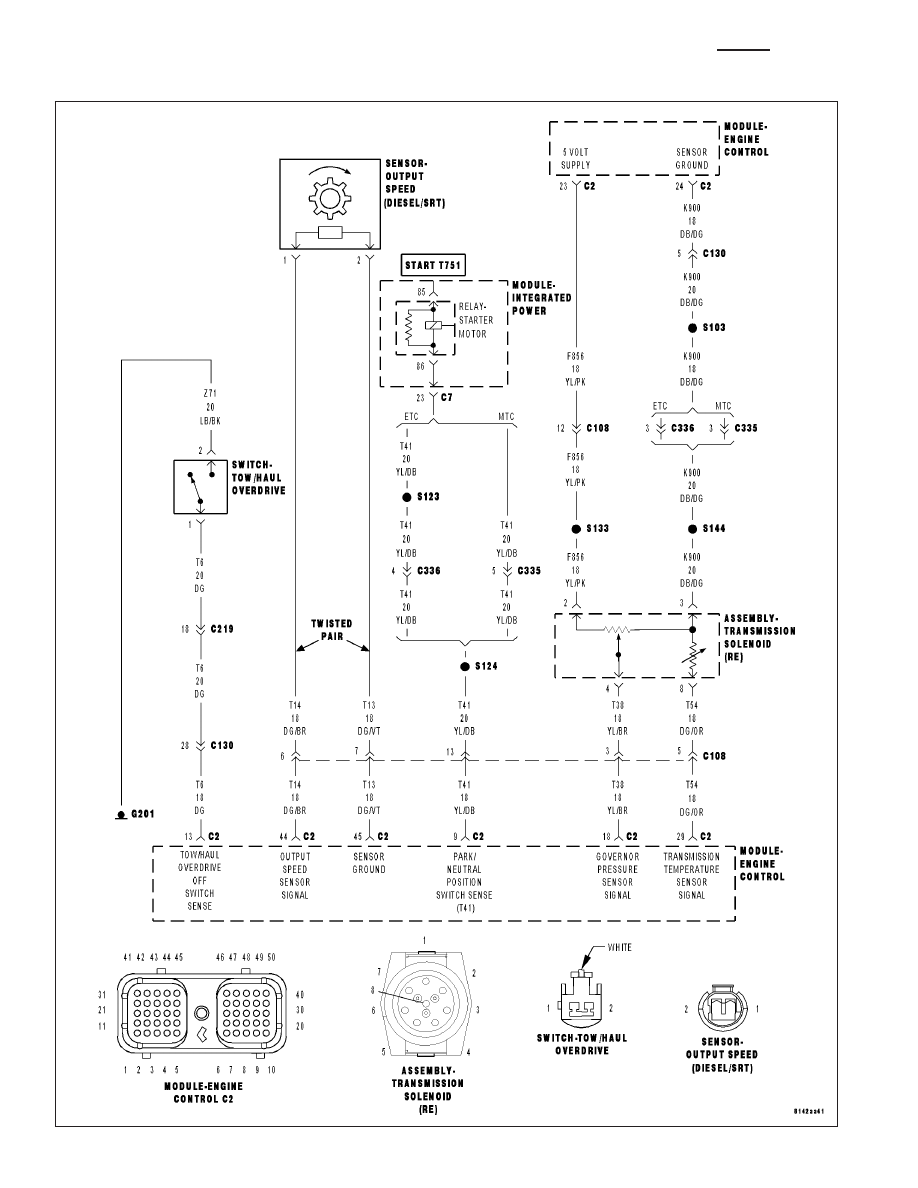
*TOW /HAUL OVERDRIVE OFF SWITCH (DIESEL)
21 - 960
AUTOMATIC TRANSMISSION - 48RE - DIESEL - ELECTRICAL DIAGNOSTICS
DR/DH
|
|
|
Content .. 1755 1756 1757 1758 ..
*TOW /HAUL OVERDRIVE OFF SWITCH (DIESEL) 21 - 960 AUTOMATIC TRANSMISSION - 48RE - DIESEL - ELECTRICAL DIAGNOSTICS DR/DH |