Index Dodge Dodge Ram Truck 1500-2500-3500 - service repair manual 2005 year
Search
Content .. 165 166 167 168 ..
Dodge Ram Truck 1500-2500-3500. Manual - part 167
INTERNAL MAIN RELAY OPEN — 65
5 - 96
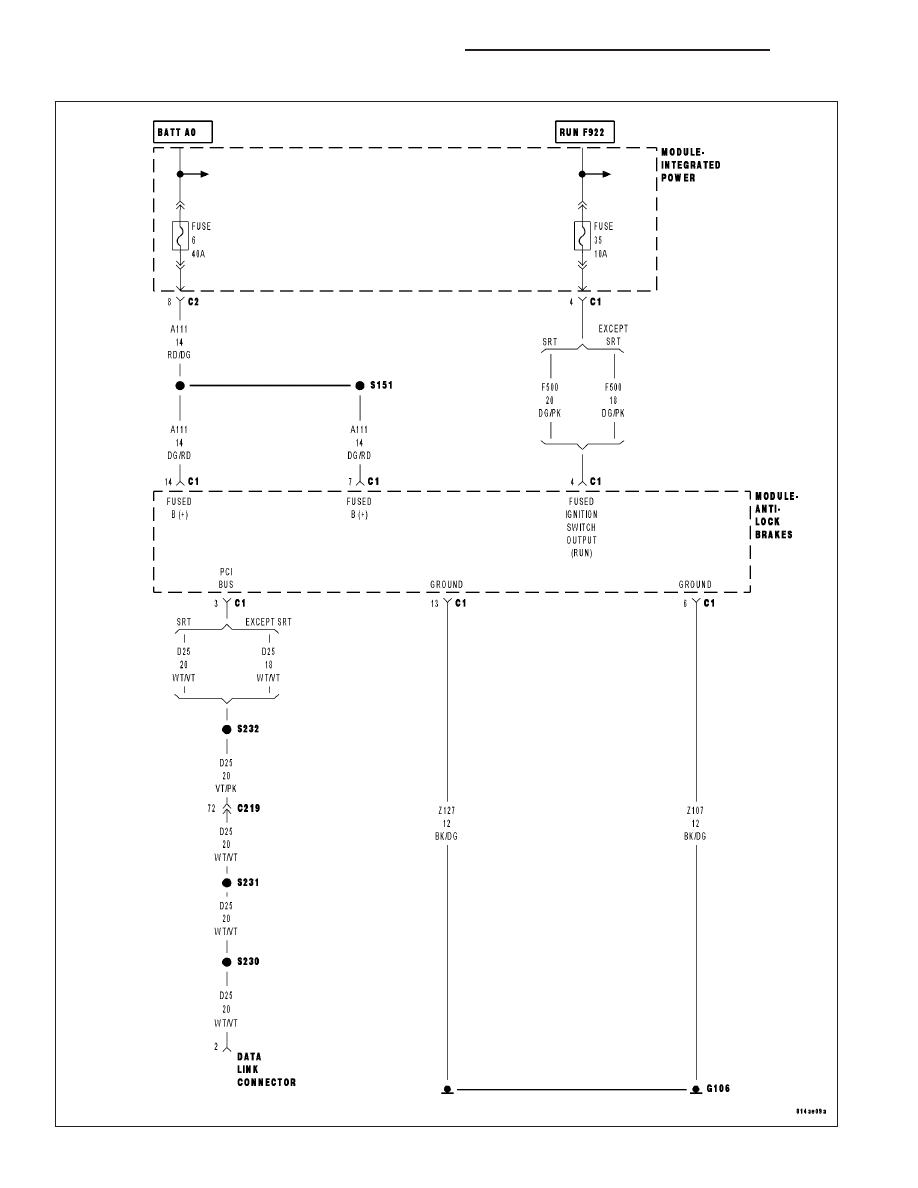
BRAKES - ABS - ELECTRICAL DIAGNOSTICS
DR/DH